Evac+Chair’s research highlights the critical need for inclusive evacuation plans across workplaces and public spaces
Evac+Chair is the original manufacturer and global leader in emergency evacuation chairs, developed for the mobility impaired.
Underpinned with over 40 years of experience in the design and UK manufacture, of evacuation chairs, Evac+Chair is trusted and relied upon in emergency situations to assist in saving lives, worldwide.
With a range of accreditations including ISO 9001: Quality Management System and ISO 13485: Medical Device Quality Management and quality checks throughout the whole manufacturing process, Evac+Chair is dedicated to manufacturing products that meet the highest of standards.
Committed to pioneering innovations for a safer and more inclusive world, Evac+Chair is passionate about ensuring that everyone can be evacuated.
Beyond access: Rethinking evacuation for true inclusivity
Since the late 1960’s we have seen the International Symbol of Access (ISA) known as the International Wheelchair Symbol, displayed worldwide, representing a place accessible for those with disabilities, in particular wheelchair users.
As our world has evolved, we have seen the introduction of the Disability Discrimination Act (DDA) 1995, later replaced with the Equality Act 2010 and slowly seen improvements in accessibility within public spaces, commercial buildings and working environments.
However, we are a long way off a fully inclusive world that is not only accessible but also supports egress, for all.
Whilst the focus has predominantly been making buildings accessible for those with impairments, a solid, robust plan for exiting is crucial to save lives.
When planning for an evacuation it is not uncommon for organisations to assume that if they do not have a wheelchair user within their workforce, evacuation equipment is either not necessary or minimal aids are needed.
However, what about those with invisible impairments? Conditions that are not obvious, such as cognitive dysfunction, injuries, chronic illnesses.
Or those with temporary impairments? Such as individuals on crutches, those recovering from surgery, or even a heavily pregnant lady whose mobility may be limited, in an evacuation situation.
For the able-bodied evacuating a building would seem easy enough, however the reality for those with a mobility impairment, is somewhat very different.
We see time and time again, when the fire alarm is raised, people pausing questioning if it is real, even stopping to collect belongings.
For the mobility impaired they are filled with trepidation, knowing they are reliant on assistance, unable to self-evacuate.
Hidden barriers: Why inclusivity matters
Risky Business, an independent study, conducted in 2023 by Evac+Chair, discussed the types of barriers people could face and highlighted the need for fully inclusive evacuation plans.
An example of a case study from this research was that of Mark, who lives in London and works as an IT support technician the 18th floor of a 25-storey building.
Mark takes medication for a mental health condition that can cause periods of anxiety, disorientation and forgetfulness.
Sometimes, this can result in him having difficulty finding his way around, even on familiar routes.
The effects of his medication may pose a risk of him being delayed in an emergency evacuation.
The latest estimates from the Family Resources Survey (FRS), run by the Department for Work and Pensions (DWP), indicate that 16.1 million people in the UK have a disability.
This represents 24% of the total population.
Currently, there are 25.3 million people who work in the UK, of which 5.53 million are disabled, a figure which is on the rise.
This highlights the importance of organisations having a fully inclusive evacuation strategy and installing the correct evacuation aids to create a space that is safe for all, which is vital to protect and save lives.
A further example of the lack of inclusivity that exists, highlighted by the Risky Business report, was that of Kira, who discussed her experience with her mobility and evacuation in her workplace.
Kira explained, “I am a wheelchair user and secured a job as a trainee in a law firm.
“As it was early in my career, I was less confident around how to approach the building managers about access barriers and evacuations.
I” kept my head down and didn’t query it, putting trust in the building manager and team.
“They assured me my Personal Emergency Evacuation Plan (PEEP) addressed that they would “assist me” in the event of an emergency.
“But when the time came to test the plan, we realised they’d assumed I could transfer myself from my wheelchair into an evacuation chair – I am unable to stand or weight-bear.
“I ended up having to drive the conversation and could sense their discomfort talking about my needs.”
Even when buildings have evacuation plans and equipment in place, there is still the need to test the plan and ensure it is suitable and fully considers the needs of those with mobility impairments.
A comprehensive evacuation plan: Ensure safety for all
Only planning for the needs of employees isn’t enough, good preparation includes those whose needs can’t be anticipated such as visitors who may require assistance during evacuation situations.
Businesses shouldn’t be left in the position of having to ask visitors ahead of their visit to disclose their disabilities, this is considered as discrimination.
Ensuring a Personal Emergency Evacuation Plan (PEEP) and a Generic Emergency Evacuation Plan (GEEP) are up to date, not only ensures the safety of those who enter your business but keeps a business compliant.
A PEEP is tailormade to ensure the safety of a specific person in the event of an emergency evacuation and must be drawn up with the individual, so that the method of evacuation can be agreed.
The plan must be clear within the organisation and for anyone who will be assisting the individual to evacuate.
Whereas a GEEP, is a more catch-all evacuation plan for buildings used by the public or places of work, with a transient workforce.
These are focused on visitors to a building who may face access barriers who are unable to self-evacuate and require assistance.
As with a PEEP the method of assisted evacuation must be clear and those who will are designated to support an individual to evacuate must understand the plan, the method of evacuation and be trained to use any evacuation aids.
Planning for the worst will keep your premises safe for all.
If an emergency does strike, a regularly tested PEEP or GEEP, alongside trained Fire Marshalls and the correct evacuation equipment are all crucial to protecting lives.
Beyond fire: The growing risk of climate change and evacuation
Typically, fires are the assumed main cause of evacuation, however there are many other risks that can be the reason for an emergency evacuation.
Global warming is becoming more prevalent year-on-year, making extreme weather and flooding a ‘when’ rather than an ‘if’.
In 2023, the most common natural disaster type in the world were floods, reported by Statista, with 164 events reported that year.
Currently, 2.27% of commercial properties in Britain are at risk from flooding.
To put that in perspective, that’s one in every four commercial properties, or 436,000 country-wide – the equivalent of all commercial properties in Greater London, Manchester, Bristol, Edinburgh, Merseyside and most of Yorkshire.
Interestingly, that is twice the rate of flood risk facing domestic properties.
As we have tragically seen, not only does this cause disruption to businesses but during this time, extreme storms and flooding have led to loss of life.
These conditions are unfortunately becoming a norm; however, preparation can ensure that lives are saved in an emergency.
Tailormade solutions: Cover all mobility needs
The global age profile is changing, with more people over the age of 64 than children under the age of 5.
This coupled with an increase in individuals working beyond the traditional retirement age of 65, highlights an even greater importance for organisations to have a fully inclusive evacuation plan.
As we age, many individuals will suffer with impacted mobility, with all of this in mind, there is a need for more to be done to ensure no one is left waiting to be evacuated, or worse lose their life.
Dedicated to the mission of accessibility for all, Evac+Chair offer solutions to suit a wide variety buildings and personnel, including a range of evacuation chairs, with payload capacity’s up to 227kg, ascent and descent evacuation, spiral and narrow staircases, with the option of 1 – 4 operators (where necessary) and a motorised, battery operated solution.
While the Evac+Chair has proven to be the safest and fastest means of evacuation, depending upon the circumstances, other evacuation aids could be more appropriate, i.e.
if an individual is unconscious or unable to get into a seated position, a ResQMat may be more suitable.
Furthermore, if the individual is unable to self-transfer, the ProMove sling, designed to wrap-around and cocoon the passenger, allowing them to be lifted and moved without the need of a hoist, is the perfect accompaniment to an Evac+Chair.
Evac+Chair offer free evacuation assessments and strongly recommend that businesses take advantage of this service before purchasing an Evac+Chair.
An experienced Evac+Chair specialist, will assess your building and select the correct model from their wide range to suit your organisation and personnel.
The assessment considers the needs of any employees who have a PEEP, alongside the type of evacuation; ascent, descent or a combination, stair configuration and evacuation route, fire exits, potential obstacles, refuge and assembly points.
Whilst an Evac+Chair is user friendly, easy to deploy and use, it is essential that all operators complete regular training, to instil confidence and competence.
Courses are available nationwide, conducted by dedicated Evac+Chair training consultants.
Training is hands-on, allowing delegates to not only understand the practical operation but experience the Evac+Chair from a passenger’s perspective too.
Alongside training, it is essential to invest in annual maintenance to ensure your Evac+Chair remains fully operational throughout its lifetime and ready to use in an emergency.
Evac+Chair offer 1-, 3- and 5-year maintenance contracts to help keep business compliant with the PUWER Regulation (Provision and Use of Work Equipment Regulations – UK only).
Maintenance includes a full, physical inspection, replacement of any worn or damaged parts, that no other third party can supply.
Book your free evacuation assessment today and ensure your personnel and visitors are safe. Tel: +44 121 706 6744. Email: enquiries@evacchair.co.uk. Visit: evacchair.co.uk.
Jonathan Gordon, Fire and Industrial Marketing Manager at Nightstick, shares how advanced materials and rigorous testing make tools durable enough to endure extreme conditions
When you’re throwing tomahawk steaks on the Griswold cast iron at midnight in the Alps, almost any light will do: spread some light, season generously, bit of oil, sizzle, spoon some hot butter and let it rest.
But when gearing up for a water rescue or a hazardous structure fire, those lights stay at home.
It begs the question: what separates a flashlight built for survival from one that’s just popular or convenient? Is it really engineered for performance, or is it mostly riding on hype?
You can’t afford cheap lights
Studies show that equipment failure accounts for a significant percentage of mission inefficiencies and safety risks.
Whether it’s a light failing to function in extreme temperatures or a casing cracking under impact, the setbacks can range from delays in victim recovery to putting the rescuers in danger themselves.
Dependable lighting must withstand the extreme conditions pros face daily: high temperatures in burning structures, submersion during flood rescues and exposure to hazardous chemicals in industrial accidents to name a few.
This is where certifications like ATEX, IECEx and UL become critical.
These globally recognized standards ensure that lighting tools are rigorously designed and tested to prevent ignition risks in explosive environments.
By adhering to strict criteria for energy limitation, thermal management and enclosure integrity, these certifications provide assurance the equipment won’t introduce new hazards, even in the most volatile conditions.
It’s in these same conditions where the rugged stand tall from the gimmicky.
The science in the components becomes essential here.
Advanced materials like glass-filled nylon and polycarbonate-acrylonitrile butadiene syrene, commonly called PC-ABS, are carefully crafted to show out in harsh conditions.
These designs leave zero doubt Nightstick gear doesn’t just survive; it performs in the rough when lives depend on it.
As we push beyond the smoke, we’ll examine how these materials exhibit intentional engineering and create solutions capable of meeting the extreme demands of firefighting and rescue operations.
Understanding the environmental challenges
Whether it’s the searing heat of a fully involved structure fire or the unpredictable hazards of a flood rescue, lighting equipment must withstand the most brutal conditions.
In fires where temperatures typically go above 260°C, tools like flashlights regularly face intense radiant and ambient heat.
Without robust materials, a flashlight warps, internal components may fail and battery performance will degrade rapidly.
Glass-filled nylon, a composite material reinforced with embedded glass fibers, offers exceptional strength, rigidity and heat resistance.
Its tensile strength is notably as strong as aluminum, yet it’s much lighter and corrosion-resistant.
An official beast in the heat, this substance becomes suitable in high-temperature environments.
The glass-filled nylon holds its shape, shields critical components and makes sure the light remains operational when every second matters.
PC-ABS is a high-performance thermoplastic blend known for its toughness and impact resistance.
Firefighters and rescue teams don’t handle equipment gently.
Not because they don’t care, but because the focus is on the mission, often times demanding speed and agility.
Lights are dropped, struck by falling debris and dragged through confined spaces.
A weak casing or poorly designed housing can mean catastrophic failure or a short life when it’s needed most.
For example, urban search-and-rescue teams often operate in unstable structures where equipment might take repeated impacts.
Materials like PC-ABS shine here, offering superior impact strength and the ability to absorb shocks without cracking or deforming.
Flood rescues, chemical spills and industrial accidents expose lights to underwater conditions, corrosive substances and fine particles.
Lighting must maintain optimal performance, whether submerged in murky floodwaters or coated with chemical residue.
A flashlight with poor sealing or insufficient chemical resistance might short-circuit, leaving its user in the dark.
Nightstick considers these risks by using silicone gaskets compressed with bezels or flanges to a precise ratio, providing airtight and watertight protection.
This design allows the flashlight’s head enclosure to maintain a secure seal, preventing water, dust and chemicals from getting to its components.
Many safety-certified lights claim to be tough as nails, but when the metal meets the meat, they’re just water resistant, not even waterproof.
Let’s face it.
It’s 2025 – your light’s ability to survive a splash should be the bare minimum.
Nightstick incorporates sealed housings and materials specifically resistant to contaminants, so products last and performance remains uncompromised.
From thick tar and gasoline to corrosive chemicals like ammonia, Nightstick lights handle direct contact with messes effortlessly.
In wildland firefighting or mountain rescues, equipment can face sudden changes in altitude, pressure and humidity.
These shifts can make weaker materials crack, fog up, or break down.
Firefighters flying by helicopter to combat wildfires often deal with rapid environmental changes and their tools need to keep up.
Glass-filled nylon roars its head in these conditions since its embedded glass fibers reduce warping, prevent swelling from moisture despite temperature and pressure changes.
You’ve got enough concerns already; your light shouldn’t be one of them.
It’s clear the materials used in a light’s construction are the backbone of durability.
The two key Nightstick materials, glass-filled nylon and PC-ABS are engineered to handle the intense conditions these tools face.
Glass-filled nylon is nylon strengthened with tiny glass fibers mixed into the material.
This makes it much tougher than regular nylon, transforming it into a material that’s lightweight but as strong as aluminum.
Glass-filled nylon and PC-ABS are the cornerstones of Nightstick durability.
Glass-filled nylon, reinforced with glass fibers, resists heat above 260ºC and maintains integrity under thermal stress, avoiding warping or cracking.
PC-ABS, a robust blend of polycarbonate and ABS, excels in impact absorption and flexibility, allowing it to withstand the rigors of rescue operations without failing.
Together these materials keep Nightstick lights reliable and effective, even under the most extreme conditions.
Nightstick LED lights use glass-filled nylon for parts like the flashlight head, where heat resistance and strength are critical.
For the body and grip, PC-ABS is the ideal choice because it absorbs shocks and offers a firm, reliable grip.
Each material is chosen for what it does best and together they make a flashlight worthy for the rugged demands of firefighting and rescue work.
Testing and validation
The durability of lighting equipment isn’t only about design or materials—it’s about proving those elements can handle the harsh realities firefighters face.
Here in Texas at Nightstick, rigorous testing processes validate the performance of our lights under extreme conditions.
These tests simulate real-world scenarios, ensuring that every flashlight is ready for the challenges of the everyday work.
Pushing limits with heat and cold
Thermal extremes are a constant in firefighting. To validate performance, Nightstick flashlights undergo testing in temperatures as high as 420°C.
This ensures the housing maintains its structural integrity, keeping components secure and free of deformation or leaks.
The process begins in an industrial-grade oven where flashlights are exposed to high heat.
For certification purposes, lights are evaluated to confirm they hold their shape, protect internal components and remain free of liquid release or material breakdown.
This is complemented by cold-weather testing, where flashlights are frozen to -29°C to simulate the extreme cold firefighters might face during winter rescues.
These thermal tests make sure the flashlights maintain their durability and functionality, regardless of the environment.
Built to take a beating
Physical impacts are inevitable in high-stakes operations.
Nightstick evaluates the impact resistance of its flashlights through a rigorous aging and stress-testing process.
For 29 consecutive days, flashlights are placed in an oven at 80ºC to simulate prolonged exposure to heat.
After this, they are frozen to -29°C for 24 hours before undergoing immediate impact testing.
A ½ kg stainless steel structure is dropped onto various parts of the flashlight from heights of 1 foot, 1 meter and 2 meters, depending on certification requirements.
This simulates real-world scenarios like drops, collisions and accidental impacts.
The goal? Making sure the flashlight keeps sprinting after years of physical stress without cracking, deforming, or losing a drop of functionality.
Keeping dust and water out
Ingress Protection (IP) ratings help flashlights perform reliably in harsh conditions filled with dust or moisture.
Nightstick conducts detailed tests to validate resistance to both.
This involves placing the light in a sealed chamber where dust particles circulate continuously for 24 hours.
The flashlight is then connected to a vacuum pump to create suction, simulating worst-case conditions.
Afterward, technicians carefully inspect gaskets and other potential entry points to confirm no particles have penetrated the housing.
Water proofing is tested under similarly rigorous conditions.
Flashlights are exposed to high-pressure water jets or submerged to ensure seals remain intact and internal components are protected.
These tests validate IP ratings like IP67 and IP68, guaranteeing performance even in submerged or water-heavy environments.
In addition to IP ratings, certifications like ATEX and IECEx validate that flashlights are rigorously tested for both water ingress and the prevention of ignition in explosive atmospheres.
These certifications require adherence to stringent international standards, so equipment remains reliable and safe even in the most hazardous conditions encountered.
Firefighting demands the best and Nightstick delivers the best work light on the market.
When the dust settles, Nightstick lights prove their worth time and again.
Failure is not an option and Nightstick lights empower first responders to work with confidence and precision, with the peace of mind their tools are as rugged and resilient as they are.
Martin Joosen, Managing Director for LION‘s Europe Middle-East, Asia and Pacific Business territories, details their upcoming new EN-compliant gear and the balance between safety, comfort and practical functionality
LION is gearing up to release its latest range of EN-compliant turnout gear next to its also well-known NFPA Range in the first half of 2025, promising to further enhance safety and functionality for firefighters worldwide.
In this exclusive interview, Martin Joosen, Managing Director for LION’s Europe, Middle East, Asia and Pacific Business territories, shares insights into the new gear’s design, features and unique aspects.
He also discusses how this launch fits into LION Group’s broader strategy within the PPE market, shedding light on the company’s commitment to supporting those on the front lines of fire and rescue.
What inspired the development of the new EN-compliant turnout gear who is it designed for?
LION has a strong background in producing NFPA-certified turnout gear in the United States.
Regions following EN standards have their own requirements and many professional firefighters in Europe and beyond prefer gear specifically approved under those guidelines.
There was a demand for LION’s existing expertise with NFPA products to be translated into something equally reliable for EN-focused markets.
Every element of this upcoming gear’s design meets EN criteria while still offering LION signature high-grade thermal protection, breathability and ease of movement.
We put considerable emphasis on how firefighters perform physically challenging tasks, leading to design priorities shaped around practical wearability.
These suits are useable among firefighters everywhere.
Our aim is to create a product line that serves a global audience, creating a versatile solution that can handle various environments while meeting EN specifications.
Can you describe how the appearance of this turnout gear has been designed to balance practicality and visibility for firefighters?
The aesthetic ideas behind this gear’s appearance are in line with our field experience with US-based NFPA standards, where every stitch and reflective detail is tested under tough field conditions.
Our designers wanted to offer firefighters something that feels safe, comfortable and meets EN rules.
For example, by combining stripes, reflective trim and easily recognised colour contrasts, the gear stands out in smoky rooms and dim conditions.
Weight was a leading challenge, since extra layers can restrict mobility.
Engineers worked on choosing fabrics and trim that keep the gear practical, safe and noticeable without adding unnecessary bulk.
They also considered how firefighters move while responding to emergencies, so any reflective elements remain visible from multiple angles.
What are the main features of the gear that will support firefighters in their work?
Even though NFPA and EN specifications differ in some respects, each has a valuable approach to thermal resistance and comfort.
A key objective has been to create a set of turnout suits that keep firefighters agile during intense situations.
The suits feature flexible closures, sleeves shaped to allow easy arm movement and carefully chosen fabrics for breathability.
Factors like heat transfer and moisture buildup were tested to maintain dryness where possible and prevent excessive heat retention.
How does the design of this gear address the specific challenges firefighters face in high-pressure situations?
Conditions during interventions and visibility on the fireground can vary greatly, making protective garments essential for safety.
LION prioritizes maximum comfort and ergonomics while adhering to relevant guidelines.
We have strategically placed reflective elements to improve visibility from various angles and to facilitate movement.
Every detail is designed to assist first responders in navigating smoke-filled hallways.
While these features adhere to established specifications, we also explored how to arrange them so that they do not hinder movement or slow the first responder down.
This blend of flexibility and compliance with regulations enables the suit to perform effectively in challenging situations.
What aspects of this turnout gear set it apart from other options currently available?
LION has been a prominent name in NFPA-regulated markets for years.
Bringing that knowledge to an EN-compliant product has given the company a chance to bridge borders and integrate all learnings from multiple regions into those new designs.
This approach offers a global view of how turnout suits function, recognising both the protective specifications and practical requirements that frontline teams encounter.
LION chose to align with these requirements so the company could provide for firefighters whose operations follow EN guidelines.
Acquiring a certification under EN ensures that these suits fit the specific needs of users in those regions.
It offers peace of mind for departments, knowing that the gear was tested according to standards recognised in their area.
What steps is LION taking to ensure this gear is ready to meet the demands of real-world firefighting by the time it launches in 2025?
LION’s research and development teams participate in multiple committees around the world that set guidelines for fabric performance and health considerations.
These groups monitor factors like heat tolerance, breathability and how protective materials can be lighter without weakening.
Attendance at these meetings exposes the teams to new methods and tests that might eventually shape updated standards.
Everyone in the PPE community shares an interest in raising the safety bar, so discussions often revolve around scientific data, emerging technologies and ways to address known health hazards.
LION tracks and reviews the latest fabric innovations to ensure the final product delivers the optimum support firefighters require.
How did firefighter health factor into the design of the new EN-certified PPE or other LION solutions?
Firefighter health is a prominent topic these days, especially when it comes to substances that might be present in protective layers.
Organisations in many regions are asking manufacturers to be extra transparent about the chemicals they use.
In response, LION continues to look for fabrics and coatings that propose the latest level of health protection while still delivering reliable thermal protection.
A separate concern is contamination from black smoke or particles that can remain in turnout suits after certain call-outs.
New regulations often address how to handle gear cleaning and maintenance so firefighters face fewer risks from harmful buildup.
LION uses the latest available materials and makes sure to acquaint itself with the local guidelines, so LION makes the most appropriate decisions on suit assembly, like how suits are stitched and sealed.
This also means that in the world of firefighting, the definition of “clean” is evolving.
It’s no longer just about appearances; it’s about ensuring the utmost safety and protection for those who risk their lives every day.
Traditional cleaning methods might leave unseen contaminants behind, putting firefighters at risk.
But now, with RedZone CO2 Clean, we’re setting a new standard – a standard that goes beyond the surface, providing a deep, thorough clean that meets and exceeds today’s safety expectations.
RedZone CO2 Clean isn’t just another cleaning process; it’s a revolutionary approach that ensures firefighters’ gear is as clean as it can be – inside and out.
Using advanced CO2 technology, it penetrates deep into the fibers of firefighters’ PPE, effectively removing contaminants that traditional methods might miss.
This is the new badge of honor – a symbol of commitment to safety, health and the future of firefighting.
So, how clean is clean? With RedZone CO2 Clean, it’s cleaner than ever before.
It’s not just about maintaining firefighters’ gear; it’s about protecting their lives.
Choose the new standard.
Choose the new badge of honor.
Choose RedZone CO2 Clean.
With that in mind and at the same time, on the training side, LION’s latest training concept, the New Fire Training Technology (NFTT) program, balanced carbonaceous, gas and digital fire technology elements to reduce the volume of hazardous particles released during drills.
The idea is to give firefighters a realistic environment without exposing them to higher-than-necessary doses of smoke and toxins.
Looking ahead, how do you see LION’s role growing in the European fire safety market and are there other developments we can expect from the company?
Firefighters throughout Europe engage in varied tasks and many companies are addressing the need to blend high heat protection with a more manageable suit weight.
This is an ongoing challenge that we have taken on by studying how materials perform in multiple scenarios.
Development teams keep looking for layers that shield firefighters from intense conditions while allowing them to move quickly.
The company is also active in preparing new concepts for firefighters who manage a variety of incidents, from structural fires to rescues in industrial sites.
Most of these steps centre on comfort and reliability.
By tracking how well suits withstand repeated exposure to smoke or water, LION can fine-tune upcoming generations of PPE.
Survitec reveals the most common equipment and servicing failures found on commercial cargo ships—and why addressing them is more urgent than ever
Fires are a common occurrence in commercial shipping, and they occur almost weekly in the container shipping segment.
The latest figures from insurer Allianz highlight the extent of the problem, as while the number of ships lost across the industry is now at a record low, there has still been 55 total losses caused by fires in the past five years. Over 200 fire incidents were reported in 2023 alone.
Industry analysts have pointed to the use of new alternative fuels, the carriage of lithium-ion battery cargoes, and a reported increase in mis-declared dangerous cargoes, especially hazardous containerised cargoes, as being contributing factors.
Metkel Yohannes, Director of Service and Rental Solutions at Survitec, believes that inadequate fire safety inspections are a less obvious but just as important underlying cause.
“The economic downturn and the emphasis on cost reduction post-Covid have had a negative impact on fire safety,” says Yohannes. “We know from experience that some ship owners and operators are maintaining and inspecting safety equipment themselves as a way of making their budgets stretch further. Crew training is also being negatively impacted. We’re finding basic errors and oversights that do not become apparent until either the ship fails an inspection and is detained – or there is a fire.”
Small oversights, big problems: Lessons from inspections
As an Original Equipment Manufacturer (OEM) and fire safety expert, Survitec is often called upon to investigate problems or faults with fire safety equipment. Their specialist fire safety technicians routinely find deficiencies in the routine maintenance and testing of safety-critical equipment that then impact system performance, even leading to equipment failure in some cases.
For instance, Survitec was called out to a vessel after an engine room fire. The crew had managed to extinguish the fire but suspected there was a fault with their high expansion foam firefighting system. The cause of the fault was a blockage in the system. The crew had installed a new foam pump and forgotten to remove one of the protective caps.
Survitec often finds issues that indicate insufficient training or a lack of expertise. For example, the foam proportioner on a high expansion foam system should be removed and inspected regularly, yet Survitec will often find membranes are damaged or broken, which impacts the delivery of foam to the system.
Another common mistake is to mix different types or brands of firefighting foam. When this happens, the foam becomes contaminated. In one inspection of the foam tank for a helideck system, Survitec found the foam had changed from a liquid state to an almost sponge-like, gelatinous state.
The system was therefore inoperable and required major work – and considerable expense – to remove the contaminated foam, deep-clean the system, and recharge it. Fortunately, in this instance, the fault was discovered and rectified before the ship had cause to use the system, because the system would certainly have failed had there been a fire.
The backbone of safety: Routine equipment inspections
Rigorous fire safety inspections of fixed firefighting systems play a vital role in ensuring the safety of a vessel and its crew. Survitec reports that many, if not most, of the inspections they perform reveal issues that require immediate corrective measures.
Furthermore, issues related to poor maintenance or superficial inspections will generally be found across multiple systems, not just one system. For example, valves that have corroded and do not open or close properly can be a common issue across all systems.
This erosion of standards correlates directly with a troubling rise in fire safety-related deficiencies recorded on board ships in recent years. The resulting increase in ship detentions following port state control inspections underscores the real-world consequences of these lapses in safety practices.
Yohannes says: “We clearly see evidence of a slip in standards when it comes to basic safety practices. Approval stamps are being applied to fire systems and appliances that would or should not pass inspection.
“There should be more oversight, more governance, and better quality control procedures. Shipowners and managers need accredited service partners they can trust.”
Technical Sales Manager at Survitec, Jan-Oskar Lid, confirms that while paperwork might indicate that a service inspection has been carried out, the levels of wear and tear on the equipment can sometimes suggest otherwise. “Some issues are self-evident – for example, the rust on a valve or a fire extinguisher is clear to see, but other issues are less obvious and can have catastrophic consequences.”
Lid quotes an example. In early 2024 a bulk carrier left port, having just completed a fire safety inspection and received full certification from a local service provider. Shortly after leaving port, a fire started in the engine room.
The crew released the CO2 system, which had just been inspected and approved, yet more than half the cylinders failed to activate. The fire was eventually extinguished but there was significant damage to the vessel, with costs of US$2-3 million for off-hire and repairs.
Lid also points out that this is not just an issue for older vessels. Inspections are just as essential for new vessels, to verify that new equipment is fully operational. For example, a CO2 system will be disabled, for safety, while a ship remains in the shipyard.
It is not uncommon for Survitec service technicians to discover that a new ship has been sailing without a functioning CO2 firefighting system, because the pilot hoses for the main control valves and release cabinets have not yet been reconnected, and safety pins are still in place.
Procuring the right parts
The procurement of spare and replacement parts can also be a challenge for ship owners and operators. Without the relevant training or expertise, it can be difficult for purchasing personnel to recognise low-quality or counterfeit parts, or even the “right” part.
High pressure hoses for CO2 fire extinguishing systems are a key example. Hoses approved for use on a high-pressure CO2 system can be distinguished by the pin pricks that run along the length of the hose, and by the Type Approval Test certificate details which will be stamped into the crimping neck, as mandated by the class societies. Poor-quality or counterfeit parts will not have these features, but the purchaser needs to know what to look for.
Revised guidelines for the maintenance and inspection of CO2 systems were published in 2021 (MSC 1318 Rev.1), to help protect seafarers against the dangers of leaking gas. Yet, safety inspections often uncover serious issues.
Hydraulic hoses are often mistaken for high-pressure hoses and improperly used in CO2 systems, risking failure under pressure. Deviations from datasheet specifications, ill-fitting hoses forced with copper washers, over-crimping, blocked or peeling hoses, and the use of multiple connections—all contrary to best practices—highlight lapses in inspection and maintenance routines.
Evaluating service provider credentials
Survey reports from Survitec’s global network of service engineers indicate declining crew competencies and skills in this respect, possibly due in part to the seafarer shortage but also the challenge of keeping on top of the various rules and regulations.
As Yohannes explains: “Service requirements are complex and varied. The International Maritime Organisation’s (IMO) MSC 1432. MSC 1432 is effectively a baseline for servicing. The vessel class and flag may specify additional or stricter requirements, and the Original Equipment Manufacturer (OEM) may have their own requirements too.
“Requirements will also vary depending on the service interval. Specialist fire safety service providers therefore invest heavily in training to provide for this.”
However, it is not always easy to identify the reputable providers. There can be a wide disparity in service quality between service providers. As Lid explains: “Cost can be the determining factor when selecting a service provider, especially when different providers boast the same approvals. Some providers may compete by undercutting their competitors, but they can often only do this by cutting corners.
“They may not invest in training to the same degree, so their technicians may lack knowledge of the different rules and regulations or the requirements for all the different brands.
“They may not even have all the equipment required to complete the inspection beyond a cursory visual check. In extreme cases, certificates may even be issued without an engineer setting foot onboard the vessel.”
Finding a provider you can trust
In its 2024 white paper Why are the fires not going out? Survitec highlights the importance of proactive measures and robust maintenance practices to ensure fire safety systems operate effectively in critical situations, also offering practical advice on what shipping companies should look for in their fire safety providers, and how to assess competency.
As Yohannes maintains, specialist fire safety service providers can play a crucial role in supporting proper and effective maintenance and testing on board ship, however trust is key. “Currently, there are no quality benchmarks, and no training standards in place to help determine competencies,” says Yohannes.
“As an industry, we should review current practices and decide: do we need more oversight, more governance, better quality control procedures around servicing and approvals?
“Ship owners and operators need accredited service partners they can trust. Anything less is not just a false economy, it’s potentially dangerous.”
Why Are the Fires Not Going Out?
Survitec’s recent white paper, Why Are the Fires Not Going Out? explores these key considerations in greater detail, offering practical advice on evaluating providers’ expertise, compliance with safety standards, and ability to deliver effective, long-term solutions. Download your free copy at survitecgroup.com
Reacton Fire Suppression’s Chief Technical Officer, Ed Barnes, shares insights into their metrology lab, international plans and engineering for accessible, high-quality fire suppression solutions
With an emphasis on innovation and quality, Ed Barnes, Chief Technical Officer at Reacton Fire Suppression, has been on a journey in engineering that his developed a commitment to delivering precision-driven, accessible fire suppression solutions.
Reacton’s state-of-the-art metrology lab ensures world-class product standards, positioning the company as a leader in the fire and safety sector.
As the industry gears up for Intersec 2025, Barnes offers insights into Reacton’s global strategy, including their ambitious plans for the EMEA region and beyond.
Can you tell me about Reacton’s metrology lab and its impact on product quality?
The metrology lab is a specialised facility for precise measurement and quality control, providing capabilities that many competitors and subcontracting engineering companies lack due to insufficient scientific tools.
To control quality to an exceptional standard, we needed the same measurement tools used in making our parts—measuring dimensions, surfaces and other physical aspects of them daily.
The metrology lab enables us to measure and control the goods we receive and those we make or machine in-house.
It’s also a diagnostics tool for finding items that may need adjusting.
If you make mechanical parts, it’s your diagnostics laboratory.
We’ve invested about a quarter of a million pounds in measurement and quality control equipment.
This allows us to build a stable understanding of the parts we receive and make.
Over time, it enables us to detect problems like dimension creep.
The equipment has enabled our team to learn and develop themselves.
They’ve learned more from measuring and monitoring than from making the parts.
We measure with micron accuracy—a micron is one-thousandth of a millimetre.
Knowing precisely what something is allows the team to make good decisions about what to do with that part.
How does the metrology lab ensure precision and reliability across Reacton’s products?
Everything we receive and make is measured precisely against every drawing.
We’re not just talking about dimensions but also measuring things like surface finish, which is crucial for seals.
If you need to keep gas in a cylinder, you need to know how the seal performs over time.
We’ve introduced helium leak detection equipment at multiple levels, which complements the metrology lab.
It allows us to measure gas leakage rates precisely. We can determine if a leak will take a day to drain a volume or 120 years.
This means every product that leaves our factory has been precisely tested and diagnosed to the standard we intended.
We’re not just assembling something and assuming it works over time; we’ve got exact numbers for days, months, years, or leak rates that meet our tolerances.
Having the equipment to diagnose what we’ve made ensures we maintain high precision and reliability across our product range.
How does the lab drive innovation in Reacton’s fire suppression systems?
The metrology lab allows us to control our tolerances more precisely.
By measuring everything accurately, we can reduce our tolerances, leading to better-performing products.
The team learns more from measuring and monitoring, which contributes to innovation.
We can detect issues early, make adjustments and improve designs based on precise data.
Having the metrology lab and equipment like helium leak detectors enables us to experiment and develop new products with confidence.
We can simulate how parts will perform, measure outcomes and iterate on designs efficiently.
This accelerates innovation in our design and development process.
How do you provide precision-engineered solutions to cost-sensitive markets worldwide?
The key is the standardisation of products.
Our concepts and intellectual property are based on common items.
Where other businesses might use different products for different markets—like vehicle fires, control panels, kitchens, or CNC machines—we use the same products across applications.
This allows us to focus our engineering control around these products.
Instead of making multiple different valves, we make one main common valve.
This means we can centre our manufacturing around one product, honing the quality and producing in volume.
Hoses, valves, nozzles, fittings and bracketry are all common components that have undergone multiple revisions.
By simplifying and standardising our components, we can purchase in larger quantities, reduce stock and maintain high quality, making our solutions accessible even in cost-sensitive markets.
We machine about 150 components in-house now, up from not making anything internally two years ago.
We brought in the metrology lab and CNC machines not to save money but to control what we make.
The variations of standard products means that we already deeply understand how the core product works.
How does the metrology lab help adapt products for diverse EMEA market requirements?
Different markets have different requirements, like pressure directives for cylinders or specific valve functions.
However, we still use common components.
The valve may undergo changes for different markets, but 90% of it remains the same as the one we originally engineered.
When adapting to a market, we don’t start from scratch; we look for the shortest path without creating an entirely new product range.
The metrology lab allows us to ensure that any adaptations meet necessary standards and regulations.
We can measure and test components to ensure they comply with regional requirements while maintaining our high-quality standards.
Most necessary adaptations have been made, so our product can be sold anywhere and meet all requirements.
How do the lab’s capabilities align with Reacton’s goals for accessible, reliable solutions?
The metrology lab’s capabilities are central to our focus on precision and accessibility.
By measuring and controlling every aspect of our products precisely, we ensure they are reliable and perform as intended.
This precision allows us to innovate confidently, knowing we can test and validate new designs effectively.
The lab also supports our goal of accessibility by enabling us to standardise components and produce them efficiently.
By controlling the quality and consistency of our products, we can offer high-quality solutions at competitive prices, making them accessible to a wider range of customers.
What recent successes or innovations stand out as impactful for both Reacton and the wider industry?
Our detection side has seen a major overhaul with new electronic components that complement the system.
We’ve refined our manufacturing processes internally, equipping our team with more tools to produce products to an even higher standard in less time.
There have been many improvements in lean manufacturing.
We’ve made significant upgrades to our system to meet traceability and quality requirements for industries like transport and military, securing future contracts in those areas.
We’ve introduced a simulation suite to simulate vibration, flow, stress, temperature and wear before producing parts, which is particularly useful for special projects with unknown variables.
Any final thoughts?
In safety engineering, you can come up with wonderful ideas to keep people safe, but if they’re impractical or expensive, they won’t be adopted.
The adoption of safety equipment depends on its feasibility. If protecting every bus costs too much, it won’t happen.
But if it’s affordable, it will. That’s where value engineering comes in.
You can create unbelievable products with broad applications by building a standard set of components honed over years.
If you’re going to do something, you do it to the best possible standard, with the best value engineering and repeatability in quality.
My career has been about identifying how we can do things better and finding ways to improve.
That comes from designing well, manufacturing to the highest standard and providing exceptional customer support.
Engineering is disruptive because you learn through failure and embracing failure is essential.
The passion for quality is crucial. It leads to finding and working with the right customers.
If your distributors and customers don’t share the same passion for quality, then you’re not in the right place.
Driving the passion for quality brings the right customers.
We use our own products in the UK; all our CNC machines use the systems we sell worldwide.
We’ve had incidents on our machines where the system has done what it’s supposed to do.
The passion for quality is the headline. For me, quality drives the right behaviours in business almost all of the time.
Esteri Group explains how its CAFS 2500’s advanced foam delivery system reduces water consumption and improves fire suppression
Firefighting is evolving. As new challenges arise, so too does the need for innovative, efficient, and adaptable tools.
Esteri CAFS 2500, the latest innovation from Esteri Group, marks a significant advancement in firefighting technology.
This system combines the proven reliability of Esteri® fire pumps with the modern efficiency of a compressed air foam system (CAFS). Designed with precision and versatility, the Esteri CAFS 2500 is engineered to meet and exceed the demands of contemporary fire services – a highlight of Intersec 2025.
Compressed air foam systems (CAFS) is a paradigm shift in fire suppression and has transformed modern firefighting strategies. By combining water, foam concentrate, and compressed air, these systems create foam that adheres to surfaces, cools faster, and suppresses fires more effectively than traditional water-based suppression methods.
The CAFS system utilises compressed air produced by a compressor, allowing the foam to be generated within the system itself—essentially, the foam is created directly at the fire truck’s pump. This method ensures the production of efficient and consistent fire suppression foam.
The Esteri CAFS 2500 takes this proven concept to new heights, introducing advanced engineering to ensure superior performance. By using significantly less water and foam concentrate, it enhances operational efficiency while reducing environmental impact.
Esteri CAFS 2500 delivers adjustable foam ratios ranging from wet foam (1:3) to dry foam (1:10). It delivers unparalleled flexibility across various fire types, including structural, industrial, and wildfires. The result? Faster extinguishment, reduced water consumption, and superior environmental performance.
This efficiency also makes it an exeptional operational advantage in regions where water resources may be limited.
Advanced features
Esteri CAFS 2500 introduces a range of highly developed features that excel in rescue operations while providing users with ease of use.
High foam delivery and efficiency
Delivering up to 2500 litres per minute, the Esteri CAFS 2500 is designed to suppress even the largest fires rapidly. Its powerful 18.5 kW compressor generates 2800 litres of compressed air per minute, ensuring consistent foam production. This level of performance translates to faster knockdowns, reduced water damage, and improved firefighter safety.
Precision engineering for adjustable foam ratios
The ability to adjust foam ratios allows fire services to tailor suppression strategies based on fire behaviour and environmental conditions. Wet foam ratios are ideal for immediate knockdown, while dry foam is optimal for creating barriers to contain fires.
Ease of use in high-stress environments
The Esteri CAFS 2500 is designed with user convenience at its core. Its control panel, available as a touchscreen or with physical buttons, simplifies operation by allowing firefighters to adjust foam output, pressure settings, and other parameters with ease. This intuitive interface ensures optimal performance and reliability, even in the most high-pressure scenarios, catering to diverse user preferences and operational demands.
Compact and space-saving design
One of the Esteri CAFS 2500’s standout features is its integrated design. By combining the pump and CAFS into a single unit, it optimises space, making it ideal for firefighting vehicles. Despite its compact footprint, the system is robust, durable, and easy to maintain.
Durability and reliability
The system’s IP-65-rated control panel protects against water and dust, ensuring reliability in rugged firefighting conditions. Built on Esteri’s trusted fire pump technology, the CAFS 2500 is designed for durability under extreme conditions.
Environmentally friendly and cost-effective
The Esteri CAFS 2500 significantly reduces water and foam concentrate usage. Its eco-friendly design minimises the environmental impact of firefighting operations while lowering costs associated with water transport and foam usage. For instance, the fluorine-free Class A foam mixture requires only a 0.3% concentration, aligning with global sustainability goals.
Applications across firefighting scenarios
While water has been the traditional agent for fire suppression, it is not always effective—especially for oil fires, where its use can be hazardous. Fire suppression with foam is not a new concept. In 1902, Russian engineer Aleksandr Loran revolutionised fire suppression by inventing (patented in 1924) firefighting foam, initially used to combat persistent oil fires. Since then, foam has been a vital tool in scenarios where water alone is insufficient.
The Esteri CAFS 2500 builds on this legacy with applications in:
Structural Fires: Wet foam extinguishes flames rapidly, while dry foam prevents reignition by creating barriers.
Industrial Fires: The system’s high foam delivery and strong adhesion are particularly effective in industrial settings, where rapid suppression can prevent catastrophic damage.
Wildfires: As wildfires increase globally, CAFS offers a critical solution. Dry foam blankets vegetation to prevent fire spread, using minimal water.
Different and demanding fire scenarios require a lot from firefighting equipment. The mobility of CAFS foam within hoses enables operations over extensive ranges. With foam output of approximately 2100–2300 l/min through a 75mm attack line, the horizontal reach is around 500 meters, maintaining foam efficiency and quality.
Vertically, the system achieves a reach of approximately 80 meters. Additionally, it can be configured for high-rise operations, further enhancing its utility.
Sustainability in firefighting
Modern firefighting goes beyond performance—it demands sustainability. The Esteri CAFS 2500 addresses this with:
Optimised water usage: Reduced water consumption lowers the strain on resources and minimises runoff of contaminated water.
Minimal foam concentrate consumption: Fluorine-free foams, used at a mixture rate as low as 0.3%, are both efficient and safer for the environment.
Energy efficiency: The system’s compressor is designed for minimal energy consumption, aligning with global sustainability goals.
While foam-based suppression has its challenges, including environmental concerns, its unparalleled effectiveness ensures its continued relevance. Foam manufacturers are dedicated to developing cleaner solutions, ensuring CAFS remains a vital tool in firefighting; There are scenarios where foam-based firefighting remains indispensable.
Design philosophy and maintenance
The Esteri CAFS 2500 is built around the Esteri® fire pump, resulting in a compact, space-saving solution. Key components, including the compressor, foam pump, mixing pipe, and control unit, are designed for durability and straightforward maintenance. This ensures minimal downtime and maximised operational readiness. All CAFS components can also be installed separately into the vehicle’s piping system.
The system’s clean, intuitive design reflects its purpose. Streamlined yet rugged, it symbolises efficiency and resilience, making it a reliable partner in demanding firefighting scenarios. As a visually striking piece of technology, the Esteri CAFS 2500 also underscores Esteri Group’s commitment to quality and innovation.
A legacy of innovation
The Finnish company Esteri Group has been at the forefront of fire equipment innovation since 1968. It is renowned for its reliable, high-quality products and innovative solutions, trusted by firefighters worldwide. At the heart of the company are products designed and manufactured in-house, including fire pumps, water monitors, and hose maintenance systems.
Last year at Intersec, Esteri Group introduced the Hosemaster system, revolutionising hose maintenance. This year, the Esteri CAFS 2500 takes centre stage, alongside the advanced TR 75 SHC water monitor—a compact, reliable tool designed to minimise turbulence and maximise performance.
Esteri Group continues to set new standards in the firefighting industry, combining reliability, innovation, quality, and firefighter safety – not forgetting sustainability. Visit us at our partner Darley’s booth during Intersec 2025 to experience these groundbreaking solutions firsthand. The Esteri CAFS 2500 represents a leap forward in firefighting technology. By combining superior performance, adaptability, and environmental efficiency, it addresses the evolving needs of fire services worldwide.
As fire scenarios become increasingly complex, the Esteri CAFS 2500 stands ready to deliver solutions that protect lives, property, and the environment.
By Chris Jelenewicz, P.E., FSFPE, Chief Executive Office of the Society of Fire Protection Engineers (SFPE)
Advancing performance-based fire safety and fire risk assessment design methodologies continues to play an essential role in the fire safety engineering profession.
As such, SFPE remains the leader in providing the technical tools that assist the fire safety engineer in delivering the best engineering solutions for all stakeholders for a given design project.
For example, in early 2025, SFPE will publish the 6th Edition of the SFPE Handbook of Fire Protection Engineering, which is considered the body of knowledge in our profession.
The increased use of performance-based design, fire risk assessment methods, computer models, and the increasing complexity of fire protection systems have increased the engineering rigor required to practice in our profession.
Also, as our profession becomes more complex, the public’s understanding of how fire safety engineering is practiced decreases.
Unfortunately, the qualifications for those practicing in our profession are inconsistent globally.
Some countries have elaborate licensure/certification systems that establish competence as an engineer.
At the same time, many countries do not have a means of establishing the competence of their fire protection engineering workforce.
Without an effective way of measuring competence, protecting the public’s health, safety, and welfare is difficult.
For example, an important recommendation from the Report of the Public Inquiry into the Fire at Grenfell Tower on 14 June 2017, Phase 2, released in September 2024, focused on the increasing need for competency in the fire safety engineering profession.
Part of this recommendation stated, “Designing buildings that are safe in the event of a fire requires particular skill.
It is a skill that can be acquired only by specialized education and experience worthy of formal recognition…..
The circumstances surrounding the Grenfell Tower fire show that an effective contribution from a fire engineer could have prevented the disaster by alerting the client and the principal contractor to the dangers of using aluminum composite panels with unmodified polyethylene cores and combustible insulation in the external wall of the building.”
SFPE is working on increasing the competency of the fire safety engineering workforce in various ways.
For example, SFPE has published the Recommended Minimum Technical Core Competencies for the Practice of Fire Protection Engineering.
This document establishes a framework for understanding the technical basis for this specialized engineering discipline that can be used throughout the globe.
In addition, in the United States of America, SFPE works with NCEES to develop the PE Exam in Fire Protection.
This exam is essential to the licensure of engineers in the United States.
Moving forward, SFPE will continue its work to ensure a competent workforce exists that will work tirelessly to reduce the risk of fire in our communities.
About the IFSJ Influencer
Chris Jelenewicz, CEO of the Society of Fire Protection Engineers (SFPE), has 35 years of experience as a licensed fire protection engineer.
He is a graduate of the University of Maryland Department of Fire Protection Engineering and is an SFPE Fellow.
He also is a retired volunteer fire chief.
IFSJ Influencers Edition 2024
The 2024 Influencers Special Edition of International Fire and Safety Journal is a collection of some of the most influential voices across the fire and safety industry, representing a collective following of 4.2 million.
Together, they provide a comprehensive overview of the latest developments, challenges, and forward-looking insights shaping the global fire and safety sector.
Stephanie Trotter OBE, President of CO-Gas Safety, discusses the unseen dangers of CO poisoning and advocates for crucial changes in public awareness and safety measures
Carbon monoxide (CO) poisoning is an often-overlooked but lethal hazard, claiming lives and leaving lasting impacts on survivors.
CO-Gas Safety, an independent, registered charity founded in 1995, is dedicated to preventing unintentional CO-related fatalities and injuries, supporting affected families and collecting data to drive awareness and safety improvements.
Stephanie Trotter, OBE, the charity’s President and Director, has played a crucial role in this mission.
A barrister and advocate for safety, her journey began through personal encounters with preventable accidents and tragic stories like that of Molly Maher, who lost her son to CO poisoning.
In this interview, IFSJ Editor Iain Hoey speaks with Stephanie about her work with CO-Gas Safety, the challenges in raising public awareness and her ongoing efforts to address the often-invisible dangers of CO poisoning across the UK.
Stephanie shares her insights into the importance of legislation, public education and the powerful role survivors’ stories play in driving meaningful safety reforms.
What exactly is carbon monoxide and why is it so dangerous?
CO is a deadly gas emitted from faulty cooking, heating, or other appliances powered by carbon-based fuels such as gas, coal, wood, or oil.
It cannot be detected by human senses—smell, taste, sight, or touch.
Less than 2% of CO in the air can kill in under three minutes.
Firefighters say that with the first breath you don’t know there’s a problem, by the second you might suspect something’s wrong, but by the third you’re unable to take any action.
CO is lethal because it binds to the haemoglobin in blood, which normally carries oxygen around our bodies, effectively suffocating us.
CO₂ (carbon dioxide) consists of one atom of carbon and two of oxygen, whereas CO contains one atom of carbon and one of oxygen.
CO is emitted when there is a lack of oxygen at the flame.
How is CO typically produced by faulty appliances such as cookers or heaters?
If a gas appliance is clogged with dust and debris, there will be a lack of oxygen at the flame.
If the ventilation grille or chimney/flue is blocked, or lack of air in a small room, the oxygen can quickly become depleted. Both issues can occur simultaneously.
Why can’t carbon monoxide be detected by human senses?
Humans cannot detect CO because it’s colourless, odourless and tasteless.
Some people report that pets like dogs and cats can sense something is wrong.
Other combustion products, such as aromatic hydrocarbons, can sometimes be detected by humans, but they’re not always present.
Testing a survivor’s breath or blood can be unreliable because CO quickly leaves the body, yet the person can continue to suffer injury even after removal from exposure to CO.
What are some of the key warning signs that a gas appliance might be faulty or producing CO emissions?
The fuel industry suggests that visual signs like soot or condensation can indicate CO.
A blue flame is unlikely to emit CO, while an orange flame could be a warning.
However, relying on visual signs is dangerous because CO cannot be sensed by humans.
Even an appliance with a perfect-looking blue flame can emit CO.
The only way to be certain is to test the air using a flue gas analyser or similar instrument designed to detect CO.
What steps can individuals take to prevent CO poisoning in their homes?
Any appliance powered by carbon-based fuel can emit CO if faulty.
To prevent CO poisoning, awareness of the danger is essential.
Ensure appliances are properly installed by qualified professionals according to the manufacturer’s instructions.
In the UK, this means you must by law use a Gas Safe Registered Engineer (GSE) qualified to work on that appliance.
Regular maintenance is crucial.
Adequate ventilation must be ensured so there’s enough oxygen at the flame to produce CO₂ instead of CO.
Chimneys and flues should be swept and checked by a sweep belonging to a recognised trade association.
Appliances without flues, like gas cookers and portable gas heaters, are extremely dangerous.
As an extra safeguard, purchase and install a CO alarm compliant with EN50291 in Europe.
Buy alarms from reputable suppliers, not the Internet, and substandard alarms have been recalled.
Make sure to activate the alarm correctly. CO alarms are effective at preventing death or serious injury but are not health monitors. They are designed to sound at certain levels of CO over time.
The EN standard requires that the alarm must not sound until at least 30 parts per million (PPM) of CO is sensed for two hours.
Higher levels trigger the alarm sooner.
WHO guidelines state there should be no more than 4 PPM over 24 hours.
Research indicates that even levels around these guidelines can cause brain damage in older adults.
Effects on children and babies are likely to be worse because the smaller you are, the faster CO affects you.
This is why miners used canaries as the first alert to CO.
Will gas emergency services always test for carbon monoxide if called out to a gas leak?
In the UK, there is no mandatory duty on the gas emergency service to test the air or emissions from appliances for CO.
There is no mandatory duty on Registered Gas Safe engineers to test for CO, although many do.
There is also no obligation to inform those exposed or their medics about that CO exposure.
Surely there should be a mandatory duty on engineers to test for CO whenever practicable? Ofgem, which licenses gas companies, has duties to raise awareness of CO and to customers in vulnerable situations.
After lobbying, Ofgem provided funding for gas emergency service companies run by the Gas distribution Networks which are now testing for CO but only for customers in vulnerable situations, such as those on the Priority Services Register (the sick, the poor, elderly, disabled, those with young children, or in remote areas).
Ofgem allows the networks to decide who qualifies as vulnerable.
Some companies like Cadent and Northern Gas Networks are leading in testing efforts, using CMDDA1 qualified engineers, but only about 2% of engineers have this qualification.
Even then, engineers often refuse to test if the customer is a tenant.
We have offered our expertise to help with data collection but have yet to have a meaningful meeting.
Ofgem has indicated that if the Health & Safety Executive deems CO testing a safety issue, they would need to fund testing for everyone.
Yet it seems to us that HSE is uninterested.
What policy changes or regulations do you believe are necessary to address CO safety in homes?
Firstly, awareness and prevention are crucial. Secondly, appliances and air in homes should be tested where practicable.
If CO is found, the PPM results should be provided to survivors and their medics in writing or digitally from a named engineer.
This should become mandatory.
Thirdly, test data should be collected and published with case studies where practicable.
Fourthly, blood tests should be performed on the deceased, especially where death is unexplained, as CO remains stable in dead bodies.
Lastly, victims, survivors and families should be assisted to help identify new dangers and gaps.
This body or a new one could be funded by a levy on the fuel industry and operate independently, similar to the Advertising Standards Authority in the UK.
Studies suggest that between 3 and 13 million people in the UK could be exposed to dangerous levels of CO (over 50 PPM).
What steps do you think should be taken globally to improve CO safety and prevent further tragedies?
Globally, countries need to legislate to create bodies responsible for CO safety.
Fuel companies could lobby governments to establish these bodies, and/or governments could impose legislation.
Necessary bodies include licensing authorities to ensure safe gas supply, funded by levies on fuel companies, regulatory agencies similar to the Health and Safety Executive to approve safety cases from supply companies, a national emergency service for fuel-related incidents, professional registers to ensure correct training for engineers and chimney sweeps and independent organisations to support survivors and families, collect and publish data, conduct research and suggest safety improvements.
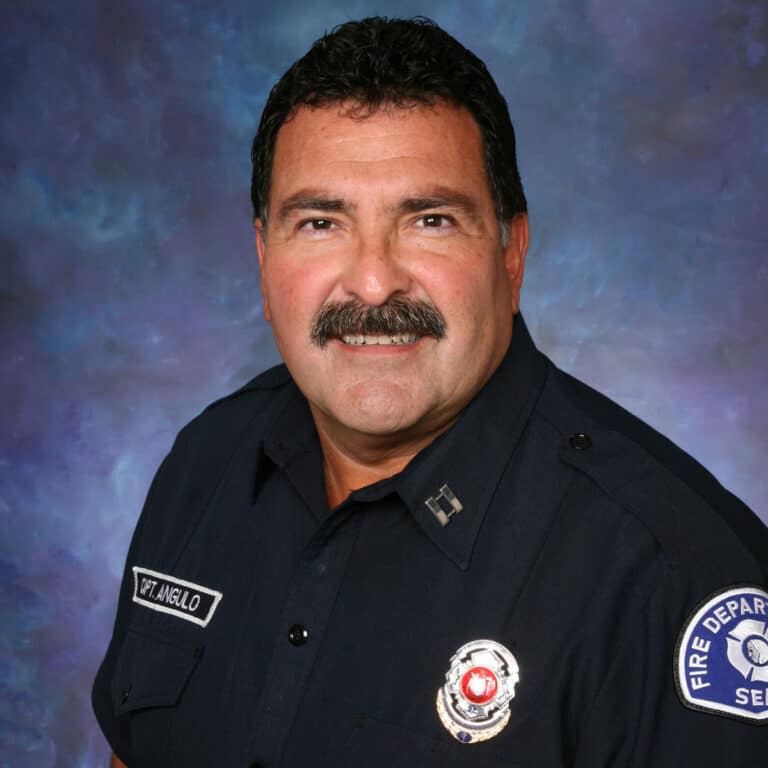
Raul Angulo provides IFSJ with his exclusive findings following detailed research.
Did the World Trade Center Building 7 (WTC 7) really completely collapse in free-fall, symmetrically into its own footprint in seven seconds due to an office fuel load fire?
I used to believe the official narrative, but now, I can no longer accept that explanation.
For many of us, this is still a visceral and emotional subject, but it’s been 23 years since September 11, 2001.
A lot of the strong sentiments have died down enough to objectively consider more reasonable, scientific, and physical (physics) explanations.
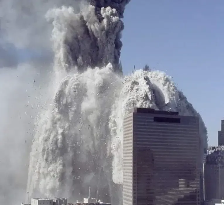
Image 1 – WTC 7 sat at the base of WTC Tower 1. (Image credit: FEMA report)
What Happened to WTC 7 on 9/11?
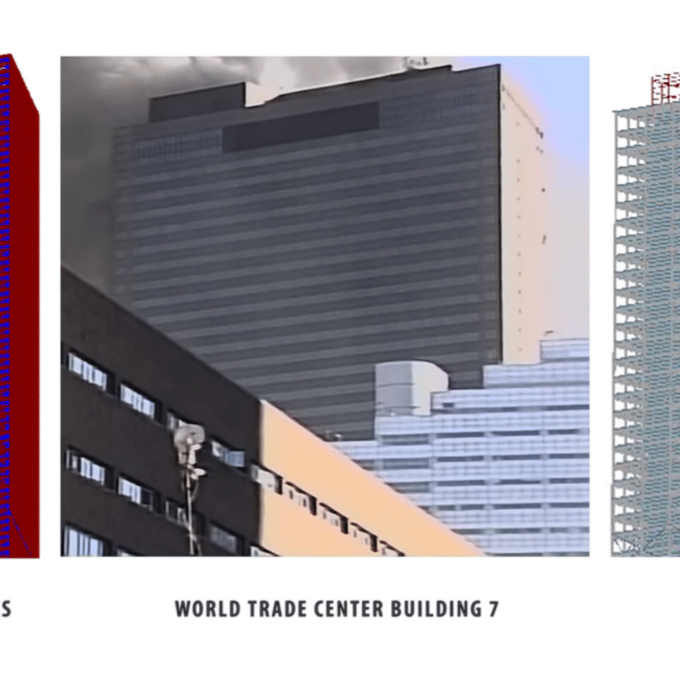
WTC 7 was a 47-story steel high-rise that stood at 610 ft. (190 m) and was clad in red granite masonry.
WTC Tower 1 was the first tower hit by a jetliner at 8:46 a.m. and collapsed at 10:28 a.m.
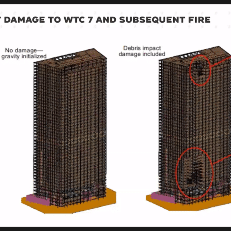
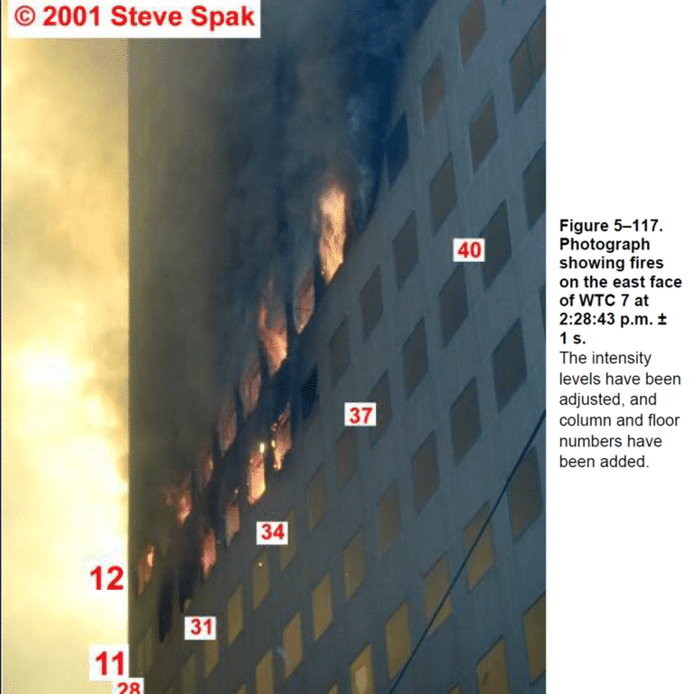
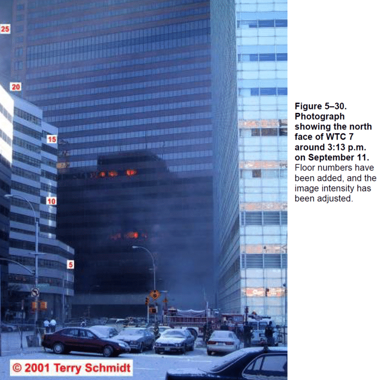
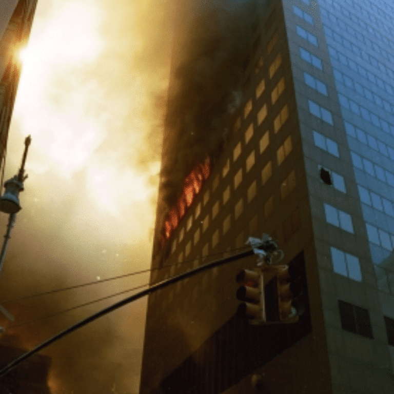
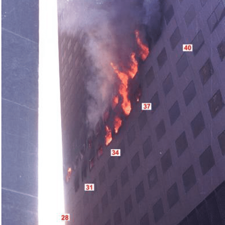
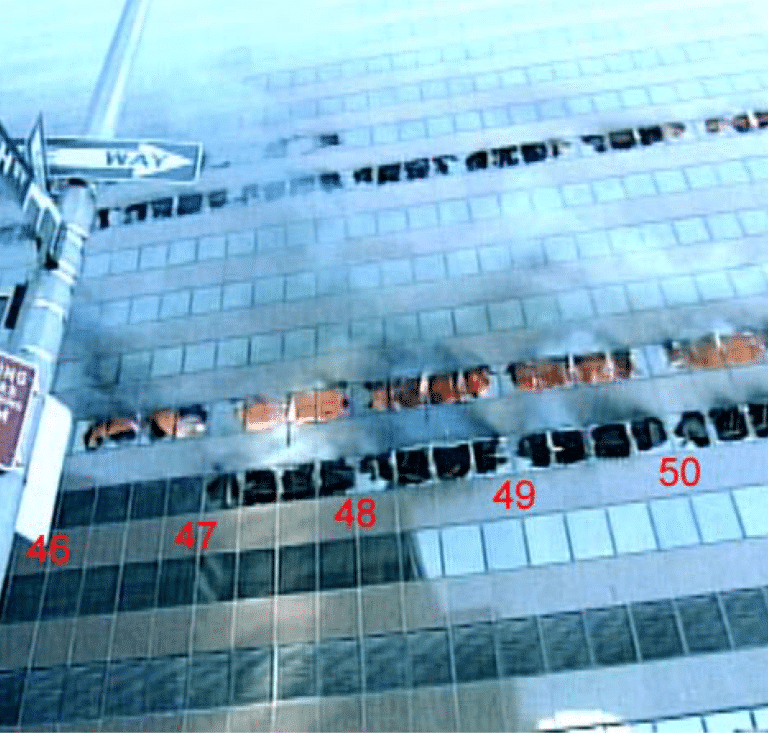
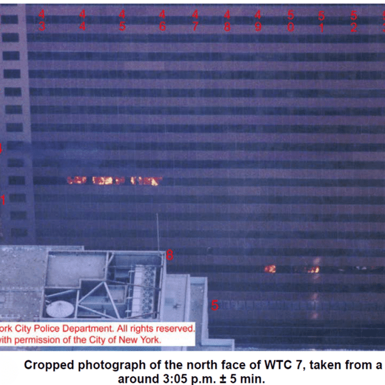
The collapsing debris of Tower 1 was claimed to have started the fire in WTC 7 (Image 2), which collapsed at 5:20 p.m., six hours and 52 minutes later.
The Lower Manhattan high-rise building was not hit by an airliner, and no firefighter lives were lost in that total collapse.
So why has the American fire service been so reluctant to discuss this subject?
Image 2 – The collapsing debris of Tower 1 damaged WTC 7 and was claimed to have started the fires in the building, which collapsed at 5:20 p.m. (Image from the NIST report)
Do High-rise Buildings Usually Collapse Due to Fire?
I’ve yet to see a training class or article on this historic incident, nor have I seen any NFPA standards changed to address the implications of this catastrophic structural failure.
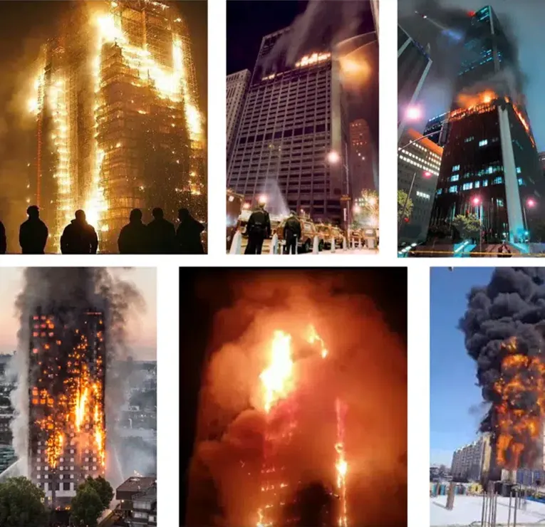
Did you know that not a single Type I Fire Resistive high-rise building has ever collapsed due to fire?
Not one in the United States, or in North America, or anywhere else in the world – only WTC 7 (Image 3).
Image 3 – Not a single Type I Fire Resistive highrise building has ever collapsed due to fire. Top L to R: Windsor Tower, Madrid, Spain 2005; One Meridian Plaza, Philadelphia, Pennsylvania USA 1991; First Interstate Bank, Los Angeles, California USA 1988. Bottom L to R: Grenfell Tower, West London, UK 2017; ABBCO Tower, Dubai, UAE 2020; Tver, Russia 2024. (Images courtesy of PAPA)
If the magnitude of this event is considered in isolation, without distractions of its historical context – in other words, had it happened in any other building, in any other city, on any other date, it would be the #1 case study in high-rise firefighting.
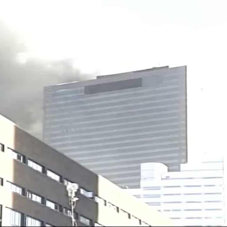
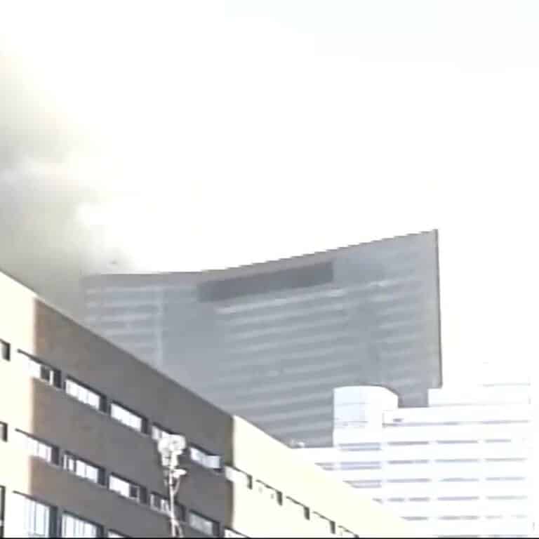
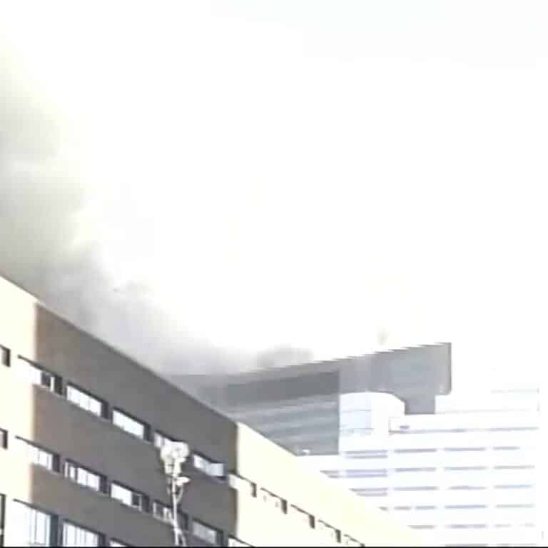
Our strategy, tactics, and standards would have been reviewed and changed to incorporate the possibility of these types of buildings falling upon us – at freefall acceleration in as short a time as seven seconds – as WTC 7 did.
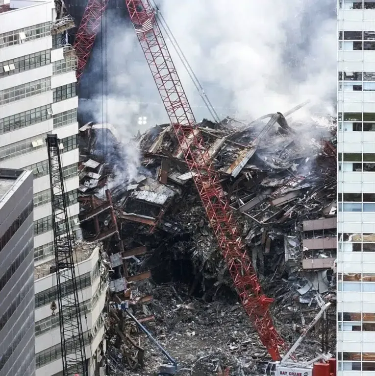
It’s not that we haven’t had collapses in highrise buildings, we have.
But they have primarily occurred during the construction phase of the building, or in portions of the building that were heavily damaged by a fire, but they have been localized collapses, area collapses, or partial collapses.
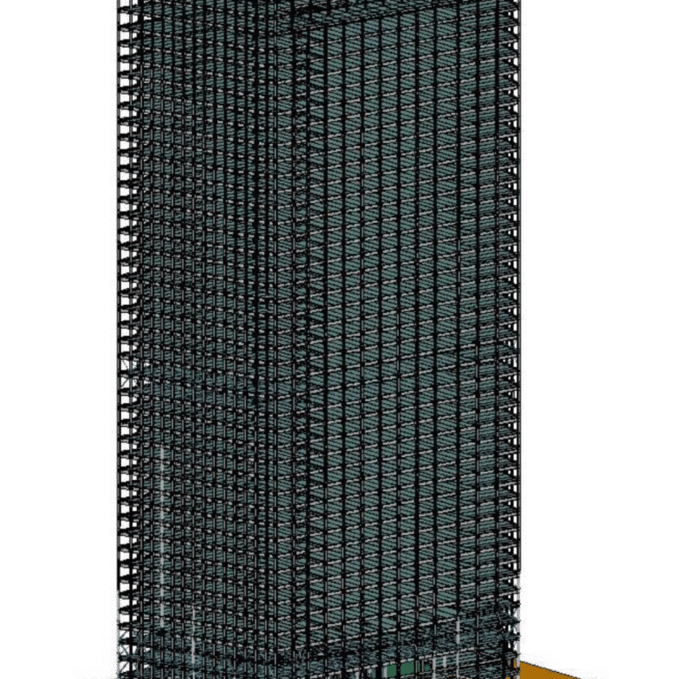
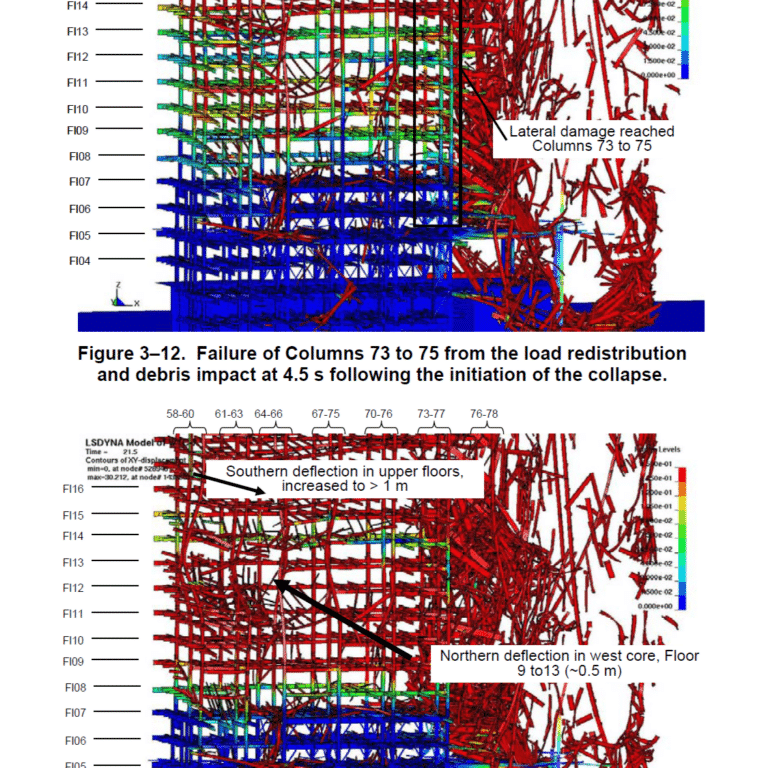
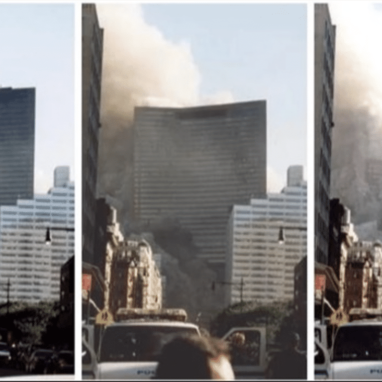
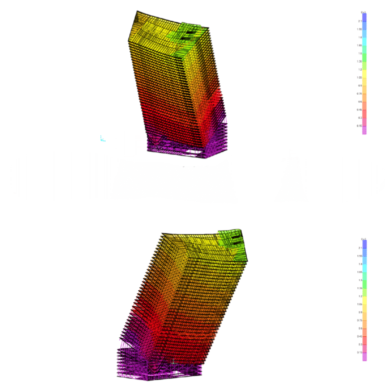
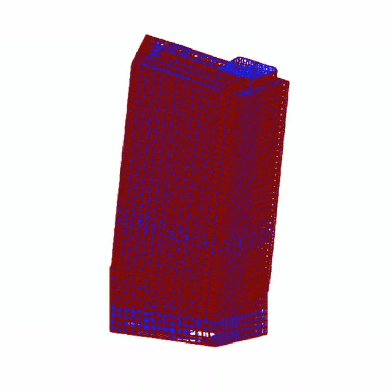
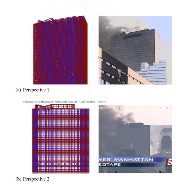
We have never had a finished and occupied highrise building experience a complete global and freefall collapse within its own footprint due to fire (Image 4).
I’d assert that this is a significant event which the fire service should revisit and objectively study until we come to agreement on the true cause of the collapse of WTC 7.
Image 4 – WTC 7 experienced a complete global and freefall collapse, and fell within its own footprint. (Image from the NIST report)
My Professional Background
I have 38 years of experience as a line firefighter and company officer, with the last 36 years spent with Seattle (WA.) Fire Department, where I retired as the senior captain.
Throughout my career, I spent an equal amount of time assigned to engine companies, as well as ladder companies (also referred to as truck companies) and worked in every district in this metropolitan city.
This includes the downtown high-rise district, so I have a strong background and extensive experience in both engine and ladder company operations to draw upon.
With over 350 published articles in all the major trade magazines, I was honored to be asked and selected to author the 4th edition of Engine Company Fireground Operations, published by Jones and Bartlett Learning in conjunction with the National Fire Protection Association (NFPA) (Image 5).
The 3rd edition needed to be updated to incorporate major advancements in the fire service.
The 4th edition ended up being an entire rewrite of the text, and I included a new chapter on high-rise firefighting.
I didn’t want this book to be a regurgitation of the same old published ideologies of firefighting, so I spent five years reading and studying every book on the subject to prepare myself for this new project.
Image 5 – Engine Company Fireground Operations 4th edition by the author. Published by Jones and Bartlett Learning in conjunction with the National Fire Protection Association (NFPA). (Image from the author)
It’s important to understand how a modern building will perform in a fire involving new synthetic fuels.
Per the request of the publisher, they wanted this edition to also include the implementation of the Underwriters Laboratories (UL) and NIST recommendations of their experiments on fire behavior with modern synthetic fuels inside lightweight wood construction structures.
This textbook would be the first to incorporate evidence-based practices for strategic and tactical firefighting.
My textbook would also carry the NFPA logo at the top of its cover.
The responsibility to author this book utilizing vetted, best accepted practices weighed heavily on me.
In addition to peer review, I knew the chapters would be scrutinized by NFPA reviewers for professional, accurate, truthful, and reliable information.
Firefighter lives would depend on its written veracity.
In the same manner, I also relied on published reference material and information from trusted authorities like NFPA, NIST, FEMA, UL, NIOSH, the National Fire Academy (NFA), and United States Fire Administration (USFA) that they are truthful, accurate, reliable, and dependable.
I trust the integrity of these agencies and organizations, along with their logos, which is their stamp of approval because ultimately, firefighter and civilian lives depend on the reliability of that information as well.
Once the book was published, I was proud and felt assured to have put out the most reliable and accurate information possible, and that this was the most comprehensive, up-to-date material on engine company fireground operations on the market.
My job was done.
But where does a book go after it’s published?
Who reads it besides firefighters?
Besides the United States, I know for a fact that copies of my textbook are now in Mexico, Canada, the United Kingdom, India, and Turkey.
I wasn’t expecting any particular scrutiny regarding selected subjects, especially in the highrise chapter.
When I was asked about the collapse of WTC 7 by numerous members of the Protecting All Protectors Alliance, I responded, rather unconcerned: “What about it?”.
I knew it had collapsed, and the information I received about the collapse of WTC 7 came from personal friends in the FDNY who were there on September 11th.
I accepted their explanation at face value and never gave it a second thought.
Then I was asked why I failed to mention this collapse as an important case study.
Had I watched the numerous videos of the WTC 7 collapse?
Did I read the NIST report on WTC 7?
Was I aware of, and did I read the University of Alaska, Fairbanks (UAF) report by Professor J. Leroy Hulsey PhD, PE, SE, Vice Chancellor for Research, and his team regarding the collapse of WTC 7?
The answer to all these questions was “No”.
I didn’t want to avoid these questions, and I didn’t want to run away from these individuals.
Most of all I wanted to defend my published work.
And these were, after all, very good questions… questions I wanted to know the answers to.
What We Know
I began with what we do know, and I say “we,” because everyone in the fire service agrees that these are the accepted definitions and classifications of high-rise building construction.
The building is our battlefield, so again, it’s important to understand how a structure will perform when it’s on fire.
Minimum construction standards and requirements are established to help maintain the structural integrity of a building during a fire for a specified period of time, usually one to four hours, so occupants can self-evacuate or be moved by the fire department to a safe refuge area within the building, away from smoke and fire.
The time ratings also offer a guide to the operational period for firefighters to extinguish the fire.
The combustibility of interior furnishings and other fuel materials gives an indication of how quickly the fire will spread.
All these criteria are essential for life safety and firefighting in highrise buildings.
Building Codes and Standards
There are two industry publications that define and classify the type of construction for high-rise buildings:
The International Code Council (ICC): Includes the International Building Code (IBC)
The International Fire Code (IFC): The NFPA 5000 Building Construction and Safety Code.
These two codes are aimed at minimizing the risk of fire, fire-related incidents, and ensuring that the minimum occupant safety requirements are met in new and existing structures.
The codes provide comprehensive regulations and criteria covering the plans, design, construction, protection, and occupancy features of buildings to minimize the dangers to life safety and property from fire, explosions, environmental impacts, like wind, snow, earthquakes, and natural disasters.
Along with NFPA 5000, NFPA 220, Standard on Types of Building Construction defines the types of building construction based on the combustibility and fire resistance rating of a building’s structural components.
Fire resistance ratings of structural elements are determined and categorized by time – in minutes or hours, in which materials, structural elements, or assemblies withstand exposure to fire in specific tests using the ASTM E119, Standard Test Methods for Fire Tests of Building Construction and Materials.
Both codes recognize five different types of construction: Type I, Type II, Type III, Type IV, and Type V. Type I refers to highrise buildings.
The IBC includes two subtypes under each category except for Type IV Heavy timber.
For example, Type I classification has column A and column B, with column A having the stronger criteria and time frames (A is stronger and better protected than B) (Image 6).
Image 6 – IBC chart for Fire-Resistance Rating Requirements for Building Elements. (Image courtesy of UpCodes)
The NFPA 5000 includes different subtypes within each building classification using a three-digit number.
Each numeral stands for hours of protection (Image 7). Type I construction is either a 442 or a 332 subcategory. 442 is stronger and better protected than 332.
First digit (X00) refers to exterior bearing walls.
Second digit (0X0) refers to columns, beams, girders, trusses, and arches supporting bearing walls, columns, or loads from more than one floor.
Third digit (00X) refers to floor construction.
The NFPA 5000 code permits Type I (442) building construction to have unlimited height, with or without automatic sprinkler systems for most buildings.
Type I (332) construction is limited to building heights of 420 feet when sprinklered, and 400 feet when unsprinklered.
Though the codes are slightly different, for all practical purposes, including for firefighting, the time ratings (in hours) for steel assemblies are basically the same.
Image 7 – NFPA 5000 chart for Fire Resistance Ratings for Type I-V Construction. (Image courtesy of NFPA)
Type I Fire Resistive Construction
This category applies to any building that stands over 75 feet in height. It includes all residential and commercial occupancies, i.e., apartment buildings, condominiums, hotels, hospitals, business offices, and other commercial spaces.
All structural members are noncombustible.
Walls, floors, columns, beams, girders, and roofs are constructed with reinforced concrete, masonry, and steel, and therefore do not contribute to the fire load of the building.
The steel is protected by a fire resistant layer of insulation.
Sprayed fire resistive materials (SFRM) are coatings that are typically “sprayed on” structural steel members and assemblies to provide insulative protection to the steel in the event of a fire.
The coatings are designed to withstand high temperatures for a long period of time without collapsing.
They’re rated by the duration of their protection, usually between 30 minutes and four hours. (Image 8).
Image 8 – The steel in WTC 7 was protected by a sprayed-on fire-resistant layer of insulation to protect it in the event of a fire. (Image courtesy of FEMA and Bernstein Associates)
SFRMs are basically categorized as cementitous, or sprayed fiber materials, which serve to insulate steel due to their relatively high thickness of cement-based products.
Cementitious materials have Portland cement or gypsum binders with light weight aggregate (vermiculite, perlite, or expanded polystyrene beads) that has some type of cellulosic or glass fiber reinforcement.
It creates a slurry when mixed and is sprayed primarily on beams and columns.
Typical application is ½-inch in thickness or greater depending on the product and dimension of the steel members. The layer may require embedded reinforcement such as mesh depending on the product.
Sprayed fiber materials are made from rock wool fibers that are manufactured from spinning molten iron slag at high temperatures.
The fiber material is mixed with a cement binder. This dry mixture is combined with water when applied.
The application thickness is similar to cementitious materials.
The testing of SFRMs is divided into two categories: one for cellulosic fires and the other for hydrocarbon fueled fires, which burn at much higher temperatures.
Fire resistance for cellulosic fires is tested per ANSI/UL 263, Standard for Fire Tests of Building Construction and Materials.
At five minutes, the temperature within the furnace reaches 1,000°F (538°C).
The temperature gradually increases during the duration of the test until at four hours, the temperature within the furnace reaches 2,000°F (1093°C).
This is considered to be the standard time/temperature curve for buildings.
Testing for resistance to hydrocarbon fire follows ANSI/UL 1709 Fire Tests of Structural Steel Protected for Resistance to Rapid Temperature Rise Fires.
In this test, a temperature of 2,000°F (1093°C) is reached within five minutes, making the test condition much more severe.
This Standard is currently considered the default fire resistance test standard in many parts of the world.
In addition, the majority of Type I buildings have HVAC systems and self- pressurizing stairwells to prevent the spread of fire.
These building systems make it easier for firefighters to access and extinguish fires (easier, not easy).
Make no mistake, highrise firefighting remains extremely dangerous and difficult, and it is the most physically challenging of all the fires we fight.
Nevertheless, extinguishing the fire stops the heat release rate and starts to lower the interior temperature.
It also reduces the production of toxic smoke and deadly fire gases.
When the fire goes out, everything gets better.
The highest priority in occupied high-rise buildings is the life safety of its occupants, which depends on protecting the stairwells to ensure the safety of evacuees.
But putting the fire out can often save more lives than a lengthy labor-intensive and sometimes chaotic evacuation, so extinguishment may be the best tactic to implement depending on the size and location of the fire.
Type I Fire Resistive buildings are extremely strong and durable.
They are also the safest buildings we have because the structural assemblies can withstand fire for an extended period of time.
Their design objectives are to prevent the partial or total collapse of a building (structural integrity), limit the spread of smoke and fire within a building (compartmentation), and limit the spread of fire between buildings (exposure protection).
In a post-September 11th response to the thermal conditions resulting from prolonged fire exposure, columns that support more than one floor now have a 4-hour rating.
Pre-9/11 it was 3-hours, which is still substantial.
For these tall buildings, the structural fire resistance performance objectives have implicitly been to prevent the collapse of a building with complete burnout of combustibles within the building, i.e., for the fire resistance of the structure to exceed the expected fire severity.
The fire resistance of a structure, or part thereof, should therefore be greater than the fire severity to which the building is expected to be exposed.
Most buildings with extreme fire loads, including commercial, residential, and institutional structures are expected to be heavily damaged by fire – but not collapse.
Rather than relying on water to control the fire, architects (and firefighters) count on the strength and durability of the construction to outlast by wide margins, the burn time of interior fuels.
It is this time-domain that has achieved such a specified level of confidence that some of these buildings are allowed to be constructed without automatic sprinkler systems, which in turn provides the assurance for fire departments to use interior strategy and tactics as the primary method to combat highrise fires.
In the High-Rise Firefighting chapter of Command and Control of Fires and Emergencies, Deputy Chief Vincent Dunn, FDNY (Retired) writes of five separate highrise attack strategies: Frontal attack, Flanking attack, Defensive attack, Non-attack, and Outside attack. Except for the Outside attack, all of these strategies are considered interior operations.
The most common strategy is the frontal attack – a direct advance onto the fire floor with a charged hose line.
It is often supported with a flanking attack and is successful in extinguishing about 95% of highrise fires.
Dunn goes on to say that if the fire isn’t controlled within the first 30 or 40 minutes, one should plan on spending hours inside the building fighting a hellish fire because the window for a quick knockdown will have passed.
Dunn states that a commercial highrise fire with an open floor area of 20,000 to 30,000 square feet (1,858 to 2,787 sq. m) cannot be extinguished by a hose team advancing a 2½ inch hose line with a 11/8 tip, or operating this stream from a stairway.
This hose line flows 260 gallons per minute (984 lpm) with a reach of about 50 feet (15 m), and can extinguish about 2,500 square feet (232 sq. m) of fire.
He writes, What really occurs at a serious high rise fire involving an entire floor or more is a controlled burn rather than a suppression operation.
Firefighters operating a hose stream maintain a defensive position in the stairway for as long as it takes for all the combustible contents to be consumed.
In one of his lectures, he stated:
“Think of these buildings as giant incinerators that far outlast the burn time of combustible materials occupying the interior space. Let the fire on the fire floor burn itself out. Think of it as a controlled burn. Efforts should be concentrated on removing occupants above the fire and stopping the vertical extension.”
I have never forgotten that statement.
In describing the defensive attack strategy, he writes:
“In a defensive attack, when a fire in a high rise is above the reach of the outside master stream, and if the frontal and flanking strategies fail, then the third option is to try a defensive strategy. This is often called the controlled burn. One or two hose streams operate from the stairway enclosure while the entire contents of the floor burns out. The fire department controls the stairways while all the combustibles on the floor are consumed. The burnout usually takes one or two hours, depending on how much combustible material is on the floor. At a defensive operation, extension to the floors above depends greatly on the type of fire resistive construction used in the building. In a defensive operation, firefighters are conceding the building to the fire. The flames are beyond the control of the fire department hand lines. Controlling the fire is now up to the fire resistance of the building itself.”
This is not a myth.
This is the conventional wisdom and accepted practice throughout the fire service in combatting highrise fires.
It is the current truth we rely on.
In fact it is this confidence in the inherent qualities in the construction of Type I fire resistive buildings that allowed the FDNY to set up their initial command posts inside the lobbies of Tower 1 and Tower 2 to hand out interior rescue assignments to all the crews.
It was this same understanding of Type I construction that also gave the Los Angeles Fire Department the confidence to remain inside the interior of the First Interstate highrise fire for the eight hour duration of the incident.
There was no fear of total global collapse, and it never did.
At the 1988 First Interstate Fire in Los Angeles, California, a building that was 62 stories and 858 feet (262 m) in height, the fire extended at an estimated rate of 45 minutes per floor and burned intensely for approximately 90 minutes on each level (Image 9).
This resulted in two floors being heavily involved at any given point during the fire. It took 4 hours and 39 minutes for firefighters to knock the fire down.
Five floors, 12 to 16, were destroyed by fire.
Total firefighting efforts took over 8 hours.
In the following months, structural engineers determined that the Type I fire-resistive building suffered no major structural damage from the fire.
Repairs were made and the building stands in service today as the Aon building.
Image 9 – At The First Interstate Bank, the fire extended at an estimated rate of 45 minutes per floor and burned intensely for approximately 90 minutes on each level. (Image courtesy of Rick McClure)
At the 1991 One Meridian Plaza fire in Philadelphia, PA, a 38 story, 492 feet (150 m) highrise, nine floors were destroyed by fire, floors 22-30.
The incident spanned 19 hours.
After 11 hours of unimpeded fire in the building, the incident commander withdrew all companies from the building fearing a structural collapse, but it never happened.
One Meridian Plaza was never reoccupied and was eventually demolished 8 years later.
So what caused the WTC 7 to collapse?
First, it’s interesting to note that in the 585 page 9/11 Commission Report which was released in July of 2004, the collapse of WTC 7 is never mentioned.
Nevertheless, different variations of the collapse hypothesis were advanced by two federal investigations: the first by FEMA in May of 2002, and the second by NIST in November of 2008.
Federal Emergency Management Agency (FEMA) Report
The FEMA report was inconclusive as to the cause of the collapse of WTC 7, but it proposed a number of scenarios for further investigation.
Based on the fact that the east penthouse fell approximately 7 seconds before the rest of the building, the FEMA Report suggests that the collapse initiated on the east side of the building interior, most likely at the transfer trusses between floors 5 and 7.
FEMA also suggested that there were not enough combustibles (office Class A fuels) on those floors to sufficiently weaken the structural members (Image 10).
Image 10 – A typical office work area in WTC 1. (Image from FEMA Report and courtesy of Port Authority of NY and NJ)
Structural steel melts at 2,732ºF (1,500ºC).
It is unlikely that a high-rise fire would be able to reach and sustain that temperature with office furnishings as its fuel load unless the steel was under direct flame contact for an extended period of time.
However, for Type I design purposes, it is usually assumed that all capacity is lost at approximately 2,200ºF (1204ºC).
The strength of steel essentially remains the same until the temperature reaches approximately 600°F (316º C).
When steel is heated to 1,000ºF-1,100ºF (538ºC – 593ºC), it loses about 50% of its load bearing capacity.
This is the failure point in fire resistance rating test like the ASTM E119.
The loss in strength and stiffness are temporary for temperatures that do not exceed 1,300º F (704ºC) for more than 20 minutes.
Even if the structural steel beams and girders are deformed, the steel will regain its pre-fire strength once the temperatures start to drop, either by the fire entering the decay stage, or if the fire is extinguished with water.
Thus, FEMA hypothesized that diesel fuel stored in the lower levels of the building was somehow pumped and discharged through severed pipes which likely fueled the fires for several hours.
he report noted that its best hypothesis had “only a low probability of occurrence” and that further investigation was needed.
NIST would later rule out the diesel fuel hypothesis.
The lack of video evidence of thick black smoke characteristic of hydrocarbon fires also confirms this fire was not fueled by a flammable or combustible liquid.
The FEMA Report also noted that the “Marriott Hotel (WTC 3), the South Plaza Building, U.S. Customs building, 90 West Street, Banker’s Trust Building, WTC 4, WTC 5, WTC 6, and WTC 7, all experienced severe damage from massive quantities of fallen debris from WTC Tower 1 and Tower 2, but arrested collapse (Image 11).
The performance of these buildings demonstrates the inherent ability of redundant steel-framed structures to withstand extensive damage from earthquakes, blasts, and other extreme events without progressive collapse.”
Image 11 – The NIST investigation claimed that WTC 7 was damaged by falling debris from WTC 1 which collapsed at 10:28 a.m. and started the fires in WTC 7. The fires would therefore burn for approximately seven hours.
The NIST Report
The NIST Report was published in November 2008. Dr.Sivaraj Shyam-Sunder is the senior science advisor for the U.S. Department of Commerce and has a science doctorate degree in structural engineering from MIT.
He is the Director of NIST Building and Fire Research Laboratory and was the lead investigator and author of the NIST Report.
Since there was quite limited physical or real forensic evidence in existence anymore, the investigation was accomplished by state of the art computer modeling, which reassembled a “virtual” WTC 7 building (Image 12).
The study and computer modeling relied on the principles of physics and science, videos, photos, and eyewitness accounts.
The evidence was gathered and analyzed. Dr. Sunder stated:
“We drew conclusions and validated them against video and photographic records.”
Image 12 – NIST’s state-of-the-art, virtual computer model of WTC 7, SW view. (Image courtesy of NIST)
This investigation claimed that WTC 7 was damaged by falling debris from WTC 1 (Image 13).
According to NIST, this started multiple fires on 10 floors which burned uncontrolled for 7 hours but were otherwise similar to fires experienced in other high-rise buildings.
They acknowledged that this extraordinary event didn’t fit with any textbook examples of our understanding of how buildings collapse during a fire.
Image 13 – Modeled impact damage to WTC 7 from Tower 1 and subsequent fires. (Image courtesy of NIST)
The report basically states that the heating and expansion of floor beams pushed a girder off its seat on a critical column, column 79 on floor 12, causing a progressive collapse of floors beginning with Floor 13, ultimately leaving the column unbraced, causing it to buckle and fail (Images 14 and 14a).
This allegedly caused a cascading internal failure up to the roof line and then for the full width of the building, followed by the exterior of the entire building in approximately 7 seconds (Image 15).
Image 14(above) – Lateral torsional buckling of floor beams at Column 79. (Image courtesy of NIST)Image 15 – Debris from the vertical progression falling onto the lower floors. (Image courtesy of NIST)
Dr. Sunder explained that the critical determining factor in the study was the thermal expansion of long span floor systems which were located on the east side of the building.
Temperatures between 1,100° F and 1,200° F (593° C and 649° C) do cause steel to lose its strength and stiffness.
Thermal expansion, however, occurs at temperatures much lower than those required to reduce steel strength and stiffness. (These temperatures were never clearly identified.)
NIST claims thermal expansion pushed the unrestricted girders (for lack of shear studs) against the supporting columns, restricting them from expanding, and causing them to buckle.
The buckling would then have caused the girder to break away from the column.
NIST claims that when fire heated the floor systems, thermal expansion caused damage to the connections between the steel beams and the concrete slabs of the composite floor systems.
Some of the beams buckled, others pushed the girders causing some of them to buckle as well.
Girders that lost their connections to the columns triggered floor failure (Image 16).
Image 16 – Vertical progression of failures. Failure of columns 77 and 78 due to Truss 2 failure from debris impact. (Image courtesy of NIST)
Furthermore, and still, according to NIST, fires on floors 7 through 9 and 11 through 13 were particularly severe.
Long-spanned steel beams on the lower floors of the east side of the building expanded significantly due to these fires damaging the floor framing on multiple floors.
Eventually, a girder on floor 13 lost its connection to a critical interior column (79) that provided its support.
The displaced unrestricted girder and other fire-induced damage caused floor 13 to collapse.
This began a cascading chain of failures of eight additional floors, many of which, according to NIST, had already been partially weakened by the fire in the vicinity of the critical column (Image 17).
Image 17 – Failure of Columns 73-75 from the load redistribution and d3bris impact at 4.5 seconds following the initiation of the collapse. Buckling of all the interior columns at 6.5 seconds following the initiation of the collapse. (Image courtesy of NIST)
The report states that fires on the four upper floors, (19, 22, 29, and 30) were of relatively short duration and inconsequential in terms of causing the collapse.
Also, while on one hand, NIST acknowledged that office fires did not persist for more than 20 to 30 minutes in a given area, which is consistent with videos, photos, and observations of the fires in the windows (Image 18), on the other hand, their fire simulation shows fires persisted on the 12th floor in the northeast corner of the building for hours and was primarily responsible for initiating the collapse by causing heat-induced failures of the 13th floor structure (Image 19).
This collapse of the south girder at Floor 13 is then alleged to have caused a cascade of floor failures on the south side of column 79 down to the 5th floor.
The west girders are said to have had their connections to column 79 broken by thermal expansion earlier and then also collapsed at this time.
Image 18(above) – If the fires started with the collapse of WTC Tower 1, then the fires started at approximately 10:28 a.m. NIST acknowledged that office fires did not persist for more than 20 to 30 minutes in a given area, which is consistent with videos, photos, and observations of the fires in the windows. This photo was shot at 2:28 pm, four hours after the fire started. (Image courtesy of NIST)Image 19 – NIST fire simulation models show fires persisted on the 12th floor in the northeast corner of the building for hours and were primarily responsible for initiating the collapse by causing heat-induced failures of the 13th floor structure. The NE corner would be to the left of the visible flames on Floor 12, yet at 3:13pm when this photo was taken, the fire on Floor 12 lacked intensity because the office fuels were burning out. Yet this fire is supposed to collapse this entire building in freefall collapse in roughly two hours. (Image courtesy of Tony Schmidt and NIST)
There were no fires on the 10th floor, which means heating could not have caused the west girder under the 11th floor to have lost its connection to column 79.
It should also be noted here that according to Building 7’s tenant list acquired from the FEMA Report, it showed that Floors 14 – 17 were vacant (Image 20).
Here, NIST claims that the same girder under Floor 13 pushed column 79 to the east far enough to break the knife connection to column 79 two stories below on the girder under the 11th floor.
It is then alleged that with the floor support gone, a series of failures left Column 79 laterally unsupported from the south and west for 9 stories, causing it to buckle, which initiated a fire-induced progressive collapse of the building.
Once Column 79 failed, the floors came down, followed by the quick succession of failures of adjoining columns.
This, in turn, caused the failure of Columns 80 and 81, and floor failures up to the roof line (Image 21).
Image 20(above) – WTC 7 Tenant List. (Image courtesy of FEMA)Image 21 – Core collapse sequence. According to NIST, once Column 79 failed, the floors came down, followed by a quick succession of failures of adjoining columns. This in turn caused the failure of Columns 80 and 81, and floor failures up to the roof line. (Image courtesy of NIST)
Does this sound reasonable? Does it make any sense?
That’s the point I’m trying to make. In numerous recorded interviews and media briefings, Dr. Sunder is quoted as saying:
“This extraordinary event, the collapse of WTC 7 was primarily due to fire…This is a new phenomenon, a new kind of progressive collapse that we have discovered here: the fire-induced progressive collapse due to thermal expansion. In fact, we have shown for the first time that fire can produce a progressive collapse… This is the first time that we are aware of, that a building taller than 15 stories has collapsed primarily due to fire…a rare event.”
These are profound statements.
So I ask again: Why isn’t the American fire service studying what should be the most important case study in the history of high-rise firefighting?
Problems with the NIST Explanations
There are several problems with the NIST explanations.
For example, there are many distorted and omitted technical factors, like the failure to acknowledge the existence of critical lateral support beams, girder side plates, and the existence of thousands of shear studs on girders in the area of column 79.
Their conclusion also doesn’t match up with the typical steel assembly behavior in fires from previous investigations of other highrise case studies, like the First Interstate Fire.
Keep in mind that WTC 7 Column 79 is an interior column.
Therefore, as with other typical interior columns, there’s a four-point connection at the top of the column for lateral support of beams or girders, so there is more steel material such as saddles, angles, bolts, and plates.
These assembly connections are exposed to less heat from the fire than the long-span steel framing members.
In temperatures below 1,100ºF (593ºC), the strength of the welds are not affected, neither are the A490 or the A325 high strength bolts.
The main question to ask is how long did the fire last, and did the fire produce temperatures greater than 1,300ºF (704ºC) for more than 30 minutes?
Think of a compass, N,S,E, and W.
With bracing imposed on all four sides, a column cannot move in any direction.
If one of the steel girders expands, it will meet strong resistance from the other three contact points at the top of the column.
Eventually the steel will weaken at the point of least resistance – mid-span of the affected beam.
The result as shown in other case studies is that the unsupported steel sags at mid-span.
It does not continue to elongate and push against the connection because the resistance forces at the top of the column are greater than the expansion force of the heated girder, and the column retains its vertical compression strength.
Even with mechanical damage, there is significant redundancy built into column design to prevent the deflection and failure of a single column to bring down an entire building in free-fall.
Sheer studs are short, unthreaded bolts welded at the top flange of a steel I-beam girder.
The shear studs are embedded into the concrete floor slab above, forming a composite beam that then acts structurally as one massive beam, stronger than the I-beam itself.
NIST has previously cited the existence of shear studs in other steel-framed highrise buildings involved in more aggressive fires as the reason for their resilience to fire-induced failure (NCSTAR, Draft 2008, p.341 and 525) (Image 22).
However, the NIST WTC 7 Final Report, states that the key girders did not have shear studs and were a crucial factor in the chain of events leading to the building’s structural failure.
On pages 347-348, NIST explained that:
“If the shear studs had been included, connecting the girder directly to the floor as a composite girder structure, the structural failure would not have occurred due to an increased lateral stiffness of the girders, preventing the floor beams from expanding freely.”
NIST used the theoretical absence of these sheer studs as a reason to explain WTC 7’s collapse, compared with other buildings that stayed upright in the face of more aggressive fires.
Image 22 – Schematic of shear stud placement relative to the metal deck. (Image courtesy of NIST)
In 2012, after a Freedom of Information Act request was granted, it has since been confirmed that WTC 7 was indeed constructed with shear studs on the beams and girders at the alleged point of failure.
In 2004, before NIST developed its hypothesis of girder thermal expansion as part of the cause of the building’s failure, it stated that sheer studs did connect the girders to the floor slabs.
This is confirmed in Professor David Ray Griffin’s research and book, The Mysterious Collapse of WTC 7 (2010, page 215), where he writes that:
“In the 2004 interim report it was specified that the crucial girder in NIST’s 2008 theory – the one connecting Columns 44 and 79 – was anchored to the floor slab with at least 22 shear studs.”
In a later 2005 draft report, NIST stated:
Most of the beams and girders were made composite with the slabs through the use of shear studs.” (NIST NCSTAR 1-1,2005)
The most obvious problem is that the explanation doesn’t match up with what we can observe on the numerous photos and videos leading up to, and showing the collapse of WTC 7.
Other international high-rise fire case studies are more spectacular than the fires burning in WTC 7.
But even though spectacular flame intensity produces higher heat temperatures that affect the strength of steel, none of these buildings collapsed.
Image 23(above) – This photo was taken at 3:05 pm and shows very little fire on Floor 12. For this fire to have caused a complete global freefall collapse, there should be flames visible from every window on Floor 12. (Image courtesy of NIST)Image 24 – This photo was taken at approximately 3:50 pm. The NIST fire simulation shows fires persisted on the 12th floor in the northeast corner of the building for hours and was primarily responsible for initiating the collapse by causing heat-induced failures of the 13th floor structure. This collapse of the south girder at Floor 13 is then alleged to have caused a cascade of floor failures on the south side of column 79 down to the 5th floor. Though all the windows on Floor 12 are broken out, there is very little, if any, visible fire in the picture. Remember that exposed steel regains its strength after temperatures start to cool. There are flames visible on Floor 8, but by this time, (3:54 pm) they should be burning down, not increasing in intensity. NIST wants us to believe this amount of fire will globally collapse this building without any resistance in the next 90 minutes. (Image courtesy of NIST)
There are numerous video angles showing WTC 7 at the time of its collapse.
Some show close ups of the building, looking up from street level.
Others, taken from a distance, have a viewpoint level with the roofline.
The closeup views show that there was lateral folding of the north face of the building along a vertical crease just before collapse.
This has been mistaken by some to be a vertical dip in the roofline.
We know it is a lateral fold because this deformation was not seen in the views, level with the roofline.
Careful measurements by independent researcher David Chandler, a high school physics teacher with a B.S. in physics and M.S. in mathematics, using tracking software, show that all of the visible corners, and several other points along the roofline transition from stationary to collapsing in absolute freefall instantaneously and simultaneously.
This is not just uniform acceleration.
It is actual free-fall, which indicates zero resistance for the first 2.5 seconds of its descent. (NIST, in its final report, shows a similar measurement for a single point near the middle of the roofline from a camera angle looking up at the building from street level, yet NIST also confirms absolute freefall for 2.25 seconds of its descent.)
The building does not tip over, but suddenly releases and falls symmetrically straight down – and falls into its own footprint (Image 25).
The entire collapse occurs in less than seven seconds!
It’s amazing to me how national fire service leaders, authors, and instructors don’t find this suspiciously alarming without demanding any professional inquiry.
Image 25 – When scientifically measured, the video of the WTC 7 collapse shows uniform acceleration and actual freefall, which indicates zero resistance for the first 2.5 seconds of its descent. When challenged by other physicists and mathematicians, NIST was forced to admit in the final report that the building did indeed collapse in absolute freefall for 2.25 seconds of its descent. The building does not tip over, but suddenly releases and falls symmetrically straight down – and falls into its own footprint. (Images courtesy of NIST)
We all know what we are looking at in the videos, at least in qualitative terms, yet NIST initially denied WTC 7 underwent a freefall collapse.
When challenged about the free-fall collapse by David Chandler, during an August 2008 technical briefing conference for members of the science and engineering community prior to the release of its final report, Dr. Shyam Sunder, director of the WTC 7 investigation, responded by stating:
“A free-fall time would be an object that has no structural components below it.”
But in the case of WTC 7, he claimed that their collapse analysis showed (according to their computer modeling) that the downward acceleration was 40% slower than free-fall.
“There was structural resistance that was provided in this particular case, and you had a sequence of structural failures that had to take place, and everything was not instantaneous.”
Another question asked by American physics professor Steven Jones Ph.D. called into question the wording used in the preliminary report “assuming constant speed,” whereas it was clear that the building was accelerating.
In answering Dr. Jones’ objection, NIST committed to revise the wording in its final report.
The final report went beyond changing the word “speed” to “acceleration” by introducing a new analysis that included a graph that confirmed a 2.25- second period of freefall collapse (Image 26).
On page 45 of the final report, NIST states:
“The north face descended at gravitational acceleration, as the buckled columns provided negligible support to the upper portion of the north face. This free-fall drop continued for approximately eight stories or 32 meters (105 ft).”
Yet NIST’s computer model shows no such period of freefall, nor did they attempt to explain how WTC 7 could have “no structural components below it” for eight stories.
Image 26 – After being challenged, the final report went beyond changing the word “speed” to “acceleration” by introducing a new analysis that included this graph that confirmed a 2.25 second period of freefall collapse. (Image courtesy of NIST)
NIST released a video animation based on its computer model which differs from videos of the actual collapse in several significant ways.
It fails to replicate the observed symmetrical collapse with sudden onset.
It shows a gradual initiation instead of a sudden release, and an asymmetrical descent with large deformations in the exterior walls that are not observed in the videos (Image 27).
The modeled building twists and tips to the east (Image 28), but the video ends prematurely after 2 seconds and doesn’t illustrate the rest of the collapse.
These inconsistencies suggest that NIST’s explanation does not adequately reflect the actual events we have witnessed, whether in person or by watching video coverage of the event.
It undermines their theory and raises questions about the validity of their conclusions.
Image 27 (above) – NIST released a video animation based on its computer model which differs from videos of the actual collapse. It fails to replicate the observed symmetrical collapse with sudden onset. It shows a gradual initiation instead of a sudden release, and an asymmetrical descent with large deformations in the exterior walls that are not observed in the videos. (Image courtesy of NIST)Image 28 – The NIST modeled WTC 7 building twists and tips to the east, but the video ends prematurely after 2 seconds and doesn’t show the rest of the collapse. (Image courtesy of NIST)
Dr. Sunder still argues that we should accept the NIST calculations because they make sense per their computer modeling, but he pushes aside the actual observational data that the building came down at absolute freefall.
Remember his quote:
“We drew conclusions and validated them against video and photographic records.”
Yet he’s later quoted in that same technical briefing:
“Here is our structural model showing the building collapsing, which matches quite well with the video of the event” (Images 29 and 30).
He’s obviously not looking at the same video I’m looking at (Image 31).
If your theory disagrees with the observed event, it’s wrong.
Image 29Image 30 Image 31 – Images 28-31 show buckling of lower exterior columns after initiation of global collapse with debris impact and fire-induced damage. Remember Dr. Sunder stated, “We drew conclusions and validated them against video and photographic records…“Here is our structural model showing the building collapsing, which matches quite well with the video of the event.” You decide if the modeling accurately resembles the video. (Images courtesy of NIST)
One of the ways we judge whether testimony is believable or not is if the person who is sharing the concept can explain it with clarity to make it understandable.
Firefighters sometimes hesitate to ask scientific questions, but you don’t have to have a Ph.D. in physics to understand the basic concepts of gravity and resistance.
How many people have played the wooden block game Jenga?
The Swahili word means ‘to build or construct.’
The game starts by stacking the 54 blocks into a solid rectangular tower of 18 layers with three blocks per layer.
The blocks within each layer are oriented in the same direction, perpendicular to the blocks in the layer immediately below.
Players take turns removing one block at a time from the tower and placing it at the top of the tower, creating a progressively more unstable structure.
The game ends when the tower collapses.
The tower always tips and falls over toward the weakest side when the forces of gravity overwhelm the resistance against it.
It doesn’t freefall, and it doesn’t fall into its own footprint.
A lumberjack cutting down a tall tree is another example.
He cuts a huge wedge into the side of the tree trunk in the direction he wants it to fall.
This is the same as removing a portion of the resistance mass of a column.
Once the wedge is cut, there’s just enough resistance to hold the tree in place.
The lumberjack then starts chopping away at the opposite side of the tree, the one that maintains the tensioned resistance.
Once that resistance point is surpassed, gravity takes over and the tree falls toward the weakest side of the trunk (the column).
If NIST’s initiation of collapse theory is true, then the building would have fallen over – toward the buckling column 79.
Albert Einstein was quoted as saying:
“If you can’t explain it to a six year old, you don’t understand it yourself.”
University of Alaska, Fairbanks (UAF) Report
The UAF Final Report, A Structural Reevaluation of the Collapse of World Trade Center 7 was a three-year study, published in March 2020 by lead investigator/author, forensic structural engineer and Department Chair, J. Leroy Hulsey Ph.D., along with Zhili Quan, Ph.D. in Bridge Engineering, South Carolina Department of Transportation, and Feng Xian, Ph.D. Associate Professor, Nanjing University of Science and Technology, Department of Civil Engineering.
Other UAF team members were from the Department of Civil and Environmental Engineering, College of Engineering and Mines, and the Institute of Northern Engineering, Fairbanks, Alaska.
The UAF report proves to be a more accurate representation of the collapse dynamics illustrated in numerous videos and it aligns with all the observable evidence.
Professor Hulsey started by using copies of the blueprint drawings that were used to construct the original Building 7, then used their computer modeling programs to reconstruct a “virtual WTC Building 7” (Image 32).
They used two independently competing, state of the art, Finite Element Analysis (FEA) computer modeling software programs (SAP2000 and ABAQUS).
They wanted their investigation to be open and transparent by inviting physicists, structural engineers, architects, fire service experts, or any interested citizen to participate.
All the data was available online as it was produced, and every aspect of their computer modeling was shared, as well as providing regular lab updates.
Image 32 – UAF virtual computer model of WTC 7. (Image courtesy of UAF Report)
The UAF research team took three approaches for examining the structural response of the building to the fire conditions that NIST claimed had occurred on September 11th, 2001.
First, they simulated the local structural response to fire loading that may have occurred below floor 13, where most of the fires of WTC 7 were reported to have occurred.
Second, they supplemented their own simulation by examining the collapse initiation hypothesis developed by NIST.
They also reviewed the collapse initiation hypothesis advanced by private engineering firms whose studies were commissioned as part of litigation related to the collapse of WTC 7.
Third, they simulated several scenarios within the overall structural system in order to determine what types of local failures and their locations may have caused the total collapse to occur as observed.
Before conducting a thorough and detailed evaluation of building response due to fire and other issues, they examined the building condition following the failure of the WTC Towers 1 and 2.
Some debris impact damage was reported to have occurred at the lower southwest corner of WTC 7, which they accounted for in simulating the building response.
Fire Did Not Cause the Collapse of WTC 7
The principal conclusion of the study is that fire did not cause the collapse of WTC 7 on 9/11, contrary to the one reached by NIST and private engineering firms that studied the collapse.
Supported by the results of its various analyses, The UAF report shows that fires could not have caused the weakening or displacement of structural members capable of initiating any of the hypothetical local failures alleged to have triggered the total collapse of the building.
Class A office fuels are not going to burn long enough to produce and sustain the elevated temperatures required to weaken and collapse the steel (Images 33a, 33b, 33c, 33d).
Nor could any local failures, even if they had occurred, have triggered a sequence of failures that would have resulted in the observed complete total collapse (Images 34a and 34b).
Image 33a(above)Image 33b (above)Image 33c (above)Image 33d (above) – Images 33a-d: The UAF principal conclusion was that the fire did not cause the collapse of WTC 7 on 9/11, contrary to the one reached by NIST. The UAF report shows that fires could not have caused the weakening or displacement of structural members capable of initiating any of the hypothetical local failures alleged to have triggered the total collapse of the building. Class A office fuels will not burn long enough to produce and sustain the elevated temperatures required to weaken and collapse the steel.Image 34a (above)Image 34b – Images 34a-b: In their computer modeling, the UAF forensic structural engineers could not duplicate the sequence of failures that would have resulted in the observed complete total collapse using the NIST criteria inputs. The building always tipped to the weakened side of the structure. (Images courtesy of UAF)
Near-Simultaneous Failure of Every Column Explains the Collapse
The secondary conclusion of the study was that the global collapse of WTC 7 involved the near-simultaneous failure of every column in the building.
This conclusion was based primarily upon the findings that only the simultaneous failure of all core columns over eight stories, followed by the simultaneous failure of all exterior columns over eight stories 1.3 seconds later, could produce the behavior observed in the videos of the collapse, whereas no other sequence of simulated failures produced the observed behavior (Images 35a, 35b, and 35c).
Image 35a (above)Image 35b (above)Image 35c – The secondary UAF conclusion was that the global collapse of WTC 7 involved the near-simultaneous failure of every column in the building on a horizontal plane. Only the simultaneous failure or removal of all core columns over eight stories, followed by the simultaneous failure of all exterior columns over eight stories 1.3 seconds later, could produce the behavior observed in the collapse videos, whereas no other sequence of simulated failures produced the observed behavior. (Images from UAF Report)
The report also stated:
“We cannot completely rule out the possibility that an alternative scenario may have caused the observed collapse; however, the near simultaneous failure of every column is the only scenario we identified that was capable of producing the observed behavior.”
They’re being nice… and professional, but in other words, they were saying NIST’s theoretical positions are untenable, they’re wrong, and in fact, impossible.
There are 81 columns on each floor across this football field-length building.
There are 8 floors of freefall (2.25 seconds) (Photo 36).
That makes 648 columns that provided absolutely no resistance.
What else can accomplish the simultaneous removal of core and exterior columns on a building-wide horizontal plane?
From my perspective, only the intentional building destruction process known as explosive controlled demolition.
But they can’t say that.
However, I can.
We all know what we’re looking at on the videos.
If it looks like a duck, walks like a duck, and quacks like a duck… it’s a duck!
Image 36 – The UAF scientific measurement of collapse velocity matches and validates David Chandler’s measurement and graph. The bold green line illustrates free fall. (Image courtesy of UAF)
Where Do We Go From Here?
As you can see, we have a big problem here.
These are two equally qualified, academically credentialed scientific bodies that have diametrically opposing conclusions regarding the cause of the collapse of WTC 7.
Their conclusions either change or confirm our accepted fire service highrise strategy and tactics in Type I fire resistive buildings.
They also change or confirm our understanding of how these buildings will react under normal fire conditions.
But who is right?
They can’t both be right.
In order to clear up the implications and confusion, we must formally review and compare both reports as a collective body of firefighters, fire prevention inspectors, and building and fire code officials.
We must then choose which conclusion seems more logical, and wrestle with the implications they may lead to (Images 37a and 37b).
Image 37a (above)Image 37b – Images 37a-b: The NIST Final Report and the UAF Report can’t both be right. Their conclusions are in direct opposition. In order to clear up the implications and confusion, the fire service community must formally and objectively review and compare both reports and respective computer models and choose which conclusion seems more logical. (Images by the author)
If the NIST report is correct, and WTC 7 collapsed from normal office fires, then the appropriate codes and standards, highrise firefighting strategy and tactics, construction, and fire safety systems need to be reviewed, changed, or updated in order to reflect the new potential risk of thermal expansion and sudden global and complete freefall collapse of Type 1 fire resistive buildings fueled by office fires.
Or, if the UAF report is correct and fire was NOT the cause of the global freefall collapse; it wasn’t even possible in their computer modeling scenarios, then WTC 7 collapsed from something other than office fires, in which case, we owe it to the public and the fire service to dutifully declare that we have determined and are in agreement that fire was not the cause of the collapse, and reassert that the current International Building and Fire Codes, and Standards related to highrise buildings, our strategy and tactics, the understanding of Type I fire-resistive construction and their behavior in normal fire conditions, and fire safety systems, are accurate, trustworthy, and reliable as currently written.
And if that’s the case, we have another problem, namely trusting the quality and integrity of major fire investigations from certain government agencies.
Too much is at stake.
Do these agencies really want to risk their credentialed professional reputations in disseminating future scientific explanations of major fire incidents and disasters?
Imagine a building collapse of this magnitude where no physical forensic evidence was preserved and analyzed.
What if the investigators for the Triangle Shirtwaist Fire, the Cocoanut Grove Fire, or the MGM Grand Fire didn’t have physical forensic evidence available for their investigation?
We wouldn’t have the life and safety code changes we have today from those fires.
Textbook Revisions
Since September 11th, 2001, Vincent Dunn has reversed many of his tactical positions for interior highrise firefighting.
To address these issues, his textbook, The Strategy of Firefighting (2007) now states that the “defend in place” strategy for occupants in highrise buildings no longer works, but relents by writing:
“However, until the fire service comes up with a better strategy than the current defend in place, the incident commander must use this plan of action at a high-rise fire.”
He also reiterates that:
“Firefighters cannot extinguish a fully involved 10-20 thousand square-foot floor area (because) they built rentable floor space too large for manual firefighting.
Chief Dunn also wrote a second edition to his book, Collapse of Burning Buildings, A Guide to Fireground Safety (2010) to include A chapter on Why the World Trade Center Towers Collapsed (Chapter 20), and High-Rise Building Collapse (Chapter 21) which is dedicated solely to the collapse of WTC 7 (Image 38).
He writes: “Now, if firefighters cannot extinguish a fire in a high rise and the blaze spreads from floor to floor, and they find themselves huddled in stairways hoping for fire-resistive construction to contain the blaze while all the office furnishings are consumed by fire (called controlled burning), then collapse of the building must be considered.
Image 38 – Collapse of Burning Buildings, A Guide to Fireground Safety, 2nd Edition by Vincent Dunn. (Image by the author)
Chief Dunn’s latest textbook, Skyscraper Battlefield (2022) includes a chapter, WTC Skyscraper 7: The Real Story of 9/11 (Chapter 22).
It basically contains the same text from the previous book, except that this identical sentence ends with “…then global collapse must also be considered.”
He goes on to define thermal expansion fire-induced collapse, “progressive collapse” and “global collapse.”
He says that the collapse of WTC 7 must be considered “a benchmark in the history of high-rise firefighting” and that fire chiefs must consider that:
The structural stability of a burning modern, lightweight high-rise, skeleton steel building must be questioned.
A high-rise can collapse after seven hours of free burn time.
10 floors of fire brought down the 47 story high-rise building.
A 47-story skeleton, steel building can totally collapse into rubble in 13 seconds.
Passive fire protection provided by the construction (designed Type I features) does not stop fire spread.
The problem with Dunn’s change of position is that he is subjectively taking all this new information provided from the NIST report as gospel.
In their new textbook, High-Rise Buildings, Understanding the Vertical Challenges (Photo 39) by Battalion Chief Jerry Tracy (FDNY, Retired), Chief Jack J. Murphy, Fire and Life Safety Directors Association of Greater New York, and Deputy Chief James J. Murtagh, FDNY (Retired) (2023), they write:
“Historically, highrise collapse failures of steel exclusively from fire have generally been localized in nature. One exception is the attack on the World Trade Center Building 7…It had been confirmed that the building had been totally evacuated…and that the building contained potentially hazardous items that would endanger the firefighters. Command determined that fighting the fire in Building 7 was too dangerous and the protection of property was not as important as the rescue efforts that day.”
Again, the rest of that section in the book covering the collapse of WTC 7 is subjectively relied solely on the information published in the Final NIST report.
It was never revealed why building contents were potentially hazardous, or why fighting the fire in Building 7 was too dangerous.
The tenant occupancy list provided in the FEMA report lists floors 14-17 as vacant.
The rest were government and financial offices. Even the New York City Office of Emergency Management (OEM) occupied Floor 23.
Image 39 – High-Rise Buildings, Understanding the Vertical Challenges by Jerry Tracy, Jack J. Murphy, and James J. Murtagh. (Image by the author)
All these textbooks from veterans of the FDNY acknowledge the possibility of this type of global collapse if the fire cannot be extinguished in a reasonable amount of time, but do not offer the normal or abnormal warning signs for the reader to prepare for an imminent fire-induced, global freefall collapse.
It’s interesting to note that the 2021 edition of NFPA 1700, Guide for Structural Firefighting (Image 40) mentions nothing of thermal expansion, fire-induced, progressive, or global freefall collapse of highrise buildings.
Image 40 – NFPA 1700, Guide for Structural Firefighting, 2021 Edition. (Image by the author)
Final Thoughts
During the writing of this word-intensive article, a couple of questions formulated in my mind that I wish to ask my fellow firefighters.
In their High-Rise Buildings textbook, Tracy, Murphy, and Murtagh wrote:
“It had been confirmed that the building (WTC 7) had been totally evacuated…”.
My question is why wasn’t the New Yort City Office of Emergency Management (OEM) which was designed to be the command center for such major events as 9/11, ever used by city and department officials?
Another point. In watching a CBS 60-Minutes program remembering the events of 9/11, Chiefs Joe Pfeifer, Peter Hayden, and Daniel Nigro were interviewed.
These were senior commanders who survived that day.
It was clear that all three of them considered the threat of a partial or localized collapse on the burning floors in Tower 1 and 2, but it was just as clear that they knew that no fire-protected steel highrise in history had ever completely collapsed due to fire.
And while they expected the fires to get worse because they did not have the ability to put them out, they never expected the buildings to come down.
The order of the day was to rescue and evacuate as many people as they could.
In regard to WTC 7, there were numerous advance warnings that Building 7 was going to collapse.
There are several video clips at the scene showing someone warning firefighters to stay back because the building was going to collapse.
Other video interviews of FDNY firefighters stated they heard explosions.
They also confirm that they heard such warnings of collapse, either from fire officials or from other sources.
In addition, there is record-preserved written testimony from firefighters of hearing explosions along with the advanced collapse warnings, hours before Building 7 collapsed.
In fact, there are about 60 FDNY firefighters who reported hearing the warnings that WTC 7 was going to collapse.
But where did this warning originate from?
The 60 Minutes interview proved it did not come from the senior command chiefs, and I would suspect that based on our common understanding of fire dynamics in Type I highrise buildings, it did not originate from the firefighters or company officers.
How could anyone have suspected or even known with certainty, hours in advance that Building 7 was going to collapse on September 11, 2001, when Dr. Sunder didn’t announce this first-time, never before seen “new phenomenon” and “discovery” of fire induced progressive global collapse until November of 2008?
So who was this person, or people who ascertained, then convinced the fire chiefs to withdraw their firefighters four to five blocks away for their own safety?
Could they have known because it was under human control?
I surmise that the firefighters did not come to the conclusion that WTC 7 was going to collapse based on observable conditions; they accepted the warning without question because they were told so by their superiors.
I’m mindful of the fact that this was not a normal day, and after the two towers unexpectedly collapsed with unbearable loss of life, including the death of 343 firefighters, one of whom was Peter Ganci, the Fire Chief of the FDNY, that the rules of firefighting had changed.
The chiefs’ expectations of how a highrise building responds when on fire were shattered and nothing would shock them anymore.
Since there was no life hazard within the building, and every firefighter was on the brink of emotional breakdown, they weren’t going to risk any more firefighter lives.
That left the freefall collapse of Building 7 to occur with little or no concern in regard to its significance or implications.
In fact, there’s a running joke within the FDNY that calls Building 7 the “Rodney Dangerfield” of high-rise buildings… it gets no respect.
This article uses common sense to follow the science and physics without emotion.
I’m not second-guessing the decisions made on 9/11.
I am trying to isolate the true cause of the global freefall collapse of a building that was on fire but not hit by a jet plane.
I shouldn’t have to apologize for asking these questions.
It has been said that physics can be cruel, and this issue is not going away.
It has to be dealt with.
There is too much information and evidence to ignore.
I have the greatest respect for Deputy Chief Vincent Dunn.
He has been a mentor and friend to me throughout my career and encouraged me to start writing in the first place, so it gives me no pleasure to challenge his work.
Since my mentor, friends, and professional colleagues were convinced to change their positions on highrise firefighting solely on the word of NIST, I would ask them to also objectively consider and carefully read the findings of the UAF report on Building 7.
Everything needs to match up with the video observations of the freefall collapse on Building 7.
The video is the key and the only convincing evidence of the reality that took place that day.
It is the integrity of our textbook writings that address and instruct the fire service on how to do our dangerous job correctly.
Civilian and firefighter lives depend on us to get it right.
There never has been a true forensic criminal investigation of 9/11, and there probably will never be one.
At minimum, if we really want to honor and remember the 343, and the thousands of other precious lives that were lost on that day, we need to petition and request that the NFPA perform an objective formal review of the UAF Report on the collapse of WTC 7 and compare their computer modeling against the computer modeling in the NIST Report in order to make a determination of true cause.
We cannot simply rely upon the official narrative issued through NIST.
The dismissive attitude toward the highly questionable inconsistencies in the NIST Report also suggests the influence of the executive branch that oversees NIST.
This article is all about establishing transparency, integrity, trust, and truthfulness.
I now view the official narrative with skepticism because it doesn’t make sense and doesn’t match with the video observable evidence.
It also does not stand up to the scrutiny conducted by the forensic structural engineers at the UAF.
NIST has declared:
“The collapse of World Trade Center 7 is the first known instance of a total global collapse of a tall building primarily due to fire. The collapse could not have been prevented without first controlling the fires before most of the combustible building contents were consumed.”
“The Great Oz has spoken!… Pay no attention to the man behind the curtain.”
– The Wizard of Oz
The links to all the reports, videos, and photographs mentioned above, as well as the NFPA petition, and the link to the fascinating must-see documentary, Calling Out Bravo-7, which exposes so much more information and evidence on the collapse of WTC 7, can be found at the website: www.ProtectingAll.org
About the Author
Raul A. Angulo is retired from the Seattle Fire Department with over 38 years of experience and is Captain Emeritus of Ladder Co. 6.
He is an international author and instructor on fireground strategy and tactics with firefighter accountability and speaks on company officer leadership and development.
He is the presenter of the popular class Drills You’re Not Going to Find in the Books and has taught at FDIC International since 1996.
He sits on the Editorial Advisory Board for Fire Apparatus and Emergency Equipment magazine and has published numerous articles in Fire Engineering.
He is also the author of the new textbook Engine Company Fireground Operations 4th Edition, published by Jones and Bartlett Learning.
References
Engine Company Fireground Operations, 4th Edition, Raul Angulo, Jones and Bartlett Learning 2021
Sudden Building Collapse, An Evaluation of a New Risk in Operational Fire Fighting, Paul S. Kayley BA (Honors) July 2016
Calling Out Bravo 7 2020 Edition, Paul S. Kayley, Video documentary
Command and Control of Fires and Emergencies, Vincent Dunn, Fire Engineering Books and Videos 1999
Strategy Of Firefighting, Vincent Dunn, Fire Engineering Books and Videos 2007
Collapse of Burning Buildings 2nd Edition, Vincent Dunn, Fire Engineering Books and Videos 2010
Skyscraper Battlespace, Vincent Dunn, Dunnbooks 2022
High-Rise Buildings, Understanding the Vertical Challenges, Jerry Tracy, Jack J. Murphy, James J. Murtagh, Fire Engineering Books and Videos 2023
Brannigan’s Building Construction for the Fire Service 6th Edition, Glenn P. Corbett, Francis Brannigan, Jones and Bartlett Learning 2021
Firefighters and Highrises 2nd Edition, Matt Stuckey, Outskirts Press 2015
Greg Young, Senior VP at Performance Advantage Company (PAC), shares insights into challenges in the tool mounting industry and their vision for future growth and innovation
Greg Young is the Senior Vice President at PAC, a US-based manufacturer specialising in innovative tool mounting systems and brackets.
With a legacy rooted in fire truck manufacturing, PAC has grown into an international company, serving sectors such as the fire service, US Navy, and other industries in need of advanced tool organization solutions.
In this exclusive interview with IFSJ Managing Editor Duncan J. White, Greg discusses the evolving landscape of tool mounting solutions, PAC’s innovative approach to addressing industry challenges, and the company’s expansion into new markets.
For those unfamiliar, can you provide an overview of PAC?
PAC is a manufacturer of specialty products of our own design. Our entire product line encompasses tool mounting solutions.
These are special products to hold and organize tools used in various settings and industries.
Born out of the fire industry, PAC has evolved over 30+ years to design and manufacture products for all industries.
The goal of PAC is to provide robust tool, mounting solutions that exceed the needs our customers regardless of industry.
We believe in our staff which has experience across multiple industries.
When we receive a request for support, PAC always has and always will apply the same philosophy: we always provide the best guidance we can.
We are here to support truck manufacturers, equipment resellers, as well as end users through their challenges around tool mounting.
There is another big thing to mention regarding what the PAC company does to serve all the industries. That is distribution and warehousing.
We go above and beyond, keeping levels of inventory that ensure our customers’ needs are met.
In addition to prompt customer service (with real people answering the phone) we’re widely known in the industry for having both extremely fast shipping and very rarely having back orders.
PAC dealers trust us for prompt drop ship orders directly to their customers.
The tool mounting sector has seen significant changes recently. In your view, what are the main challenges driving these changes?
Without question, we’re seeing the largest number of changes surrounding EV’s as well as the electrification of what were historically, pneumatic and hydraulic powered tools.
The suppression and control of EV and battery fires is still evolving. Those tools in that field are still evolving.
We’re seeing many new products come online to help firefighters extinguish, and control battery fires for example.
We’re still watching the industry evolve, knowing it will get to a place where tools and training provide a safe community.
Because these tools are relatively new in the marketplace and various manufacturers continue to bring new concepts, we haven’t yet defined a solution for some of these new tools.
PAC is known for its innovative approach. Can you share how the company identifies and response to emerging needs in the market?
As we talked about before, we often have a tool mounting kit that will work for a brand-new type of tool that just came on the market.
Our team just doesn’t have the knowledge yet to say this kit will work with this new battery cooling nozzle, for example.
So we’re not afraid to work with manufacturers directly. We’re not afraid to work with equipment dealers.
Often times tool manufacturers and dealers approach us for answers. Many of our staff members are end users in various industries. In that way, the PAC staff is excited to identify and innovate as necessary.
We respond to emerging needs in the market as both partners and participants; making careful decisions that impact the well-being and safety of people around the world as well as our own staff.
Can you tell us about any of PAC’s recent products or innovations and their intended impact on the fire service?
Over the last several years, we’ve been asked to look at fire extinguisher mounts for various reasons.
So, a few years ago we developed two products, a 3 pound and a 5 pound extinguisher holder.
These could be mounted to any vehicle or stationary surface and feature our rugged design with easy to release straps.
Building on that, we found customers asking for larger mount for 10-pound extinguishers.
We noted these requests to look at extinguisher mounts correlate to an increasing presence of smaller attack vehicles, which have nontraditional compartments.
Additionally, to fight fires – regardless of how or where they may erupt – law enforcement, landscaping and garbage trucks are carrying extinguishers.
Our new 10 pound extinguisher mount provides an additional solution for mounting oxygen bottles.
Oxygen storage has been lacking from our product line until now! We’re very excited to support our customers around the world that provide critical life saving measures.
With the complexity of tools and vehicles how does PAC ensure its mounting solutions remain relevant and effective?
We understand our products represent an investment by our customers.
For those who use our products, the feedback we receive is that the customer service, product quality and product versatility surpass other solutions.
Additionally, we stand behind our products with a limited lifetime warranty.
So, we believe PAC will continue to be effective partners of the fire industry by providing the promptest service and incredible value.
Can you share an example when PAC adapted its products based on customer input?
We listen to our customers; whether they come to us directly or we come to them at tradeshows or site visits.
For this reason, several products come to mind.
For example, a military truck manufacturer came to us requesting tool mount brackets moulded in camouflage schemed colours.
Other military customers have approached us for products to meet specific military testing requirements outside of the requirements of the fire industry.
We have created and tested several military products that are used in various scenarios around the world.
As PAC expands into new markets, such as marine and industrial sectors, what specific adaptations or innovations are being introduced to meet the unique demands of these environments?
Earlier I mentioned our new 10-pound extinguisher mount, K5046. The requests for this product came from outside of the traditional fire industry.
The design of it, and the size of it are tailored with different environments in mind.
Storage compartments as well as the access an operator has to the tools are much different between a fire truck and a fireboat, for example.
The mounting surfaces outside a utility truck are much different than what are available on a boat hull, or an agriculture roll bar.
So we’re innovating with this knowledge. Tool mounting is needed across sectors.
We’re investigating what our products need to look like for the widest adaptation across industries.
Looking ahead, what trends or technological advancements do you believe will most influence the future of tooling solutions?
We will certainly continue to look at the diversity of our products. Meaning we develop products for from the standpoint of its usefulness across industries.
An example of this is a recently modified kit K5030, Universal Saw Kit. This was originally a kit that we developed for the fire industry that has seen an introduction of electric chainsaws from all types of manufacturers.
So our kit needed to be redeveloped to accommodate all the different chainsaw platforms.
We’ve always look to develop products that have a grip range that accommodates a variety of tools, not so much a line to line fit.
There are dozens of axe manufactures, for example, and they each have different dimensions for the handle and the head, respectively.
It would be easy to design a mount for one brand and one size, but this wouldn’t build customer’s satisfaction.
The right thing to do is build for the long-haul; build for the bigger picture. That’s what we do with all of our products.
But I think the clearest trend ahead of us is the electrification of tools as well as vehicles.
The types of tools carried on a fire truck is certainly undergoing changes and that trend will likely continue for decades.
PAC has a strong presence internationally – are there any plans for further global expansion?
We’re looking for the right partners who can help us bring our high-quality tool mounting solutions to markets outside of North and South America.
This is an exciting opportunity for PAC as we continue to grow globally, ensuring that more first responders worldwide have access to the best equipment to keep their communities safe.
By building strong distributor relationships, we can maintain our commitment to fast delivery, excellent customer service, and support on a much larger scale.
Finally what are PAC’s strategic goals for the coming years, and how do you plan to continue leading in the tool mounting industry?
Well, you know that I don’t like giving away any secrets, but what I can tell you are three things.
Even as we continue to grow, we MUST do what our customers need most: When you call PAC for service or help, you always get a real person.
As challenging as the labour market is right now, or continuing to promote from within to ensure our customer service needs are met with knowledgeable and prompt service.
When a new fire truck is nearing completion at the factory; it’s time to install tool mounts into the fresh, open compartments.
PAC customers rely on our stock levels and fast shipping to moves that truck from production into service quickly.
So we continue to serve our customers with our on-site warehouse and top notch inventory control.
Finally, we will continue to share knowledge with our customers. We will continue to do in person trade shows and on site customer visits.
We will continue to expand our reach with new technologies, such as our website and email marketing.
Above all else, our mission will remain to do our part, keeping the communities around the world protected.
We’re going to do this by provide our customers the help they need when they need it most.
This article was originally published in the September 2024 issue of International Fire & Safety Journal. To read your FREE digital copy, click here.